
Display device and TV receiver

一种显示装置、显示面板的技术,应用在电视、彩色电视、照明装置等方向,能够解决显示面板的显示图像变暗、光学片褶皱等问题,达到抑制弯曲、防止褶皱、优质显示图像的效果

Inactive Publication Date: 2010-03-24
SHARP KK
View PDF1 Cites 11 Cited by
  • Summary
  • Abstract
  • Description
  • Claims
  • Application Information

AI Technical Summary

Problems solved by technology

[0004] In addition, when the light source is turned on, the temperature of the optical sheet stretches, so if the pressing force of the pressing member is strong, wrinkles will be generated on the optical sheet, and a part of the displayed image on the display panel will be darkened.

Method used


Image

  • Display device and TV receiver
  • Display device and TV receiver
  • Display device and TV receiver

Examples


Embodiment Construction

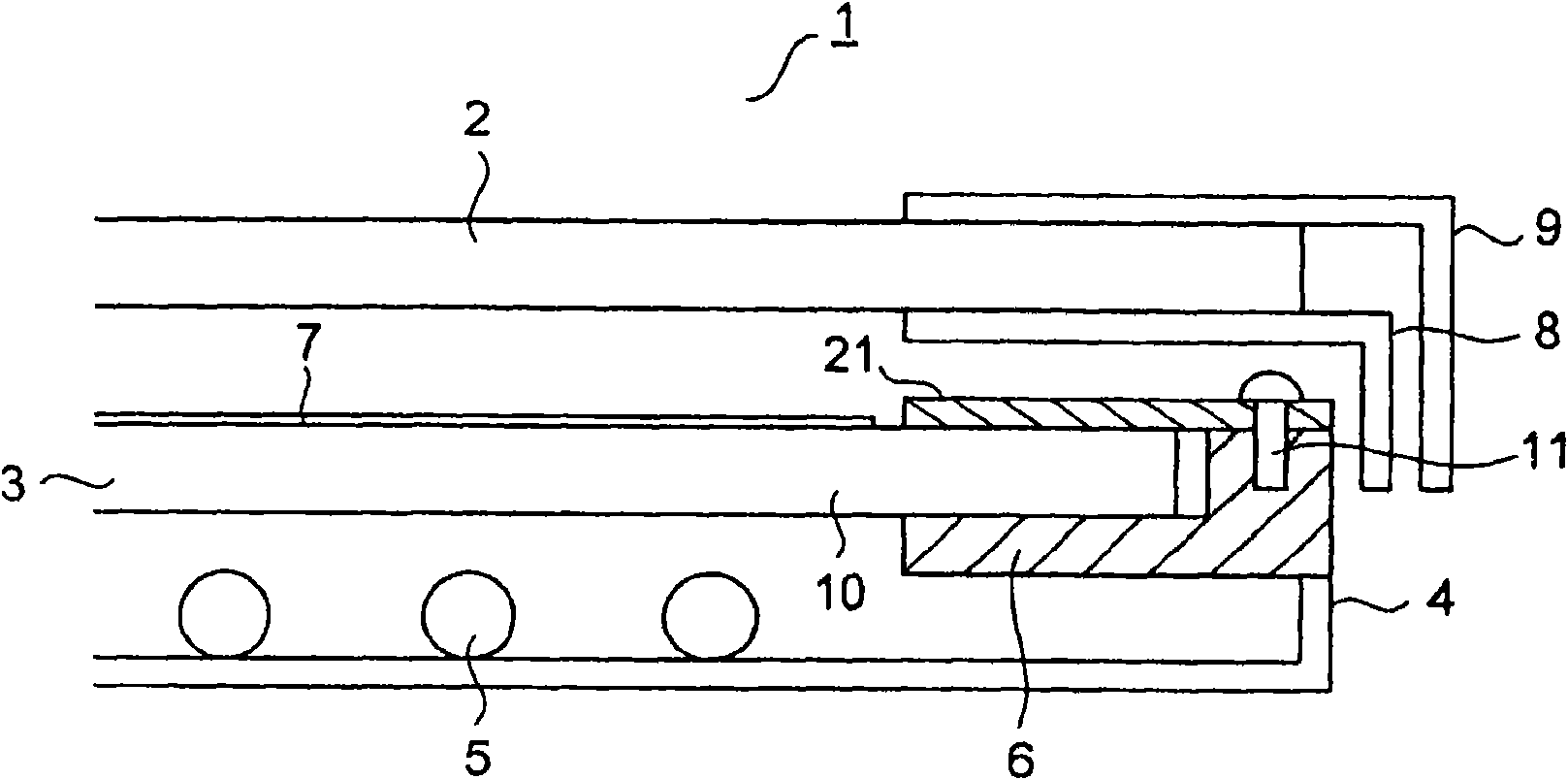
[0059] Hereinafter, embodiments of the present invention will be described with reference to the drawings. figure 1 It is a side sectional view showing the display device of the first embodiment. In the display device 1 , an illumination device 3 is disposed on the back side of a display panel 2 such as a liquid crystal panel. The display panel 2 has pixels arranged in a matrix, and light emitted from the lighting device 3 passes through predetermined pixels of the display panel 2 to display an image.

[0060] The lighting device 3 includes a rear chassis 4 covering the rear side, and holds a light source 5 through the rear chassis 4 . The light source 5 is composed of a plurality of columnar fluorescent tubes arranged at predetermined intervals. The light source 5 can also be formed by means of meandering fluorescent tubes.

[0061] A support stand 6 for supporting the diffuser plate 10 is integrally provided on the rear chassis 4 . The diffuser plate 10 is composed of a ...


PUM


Abstract

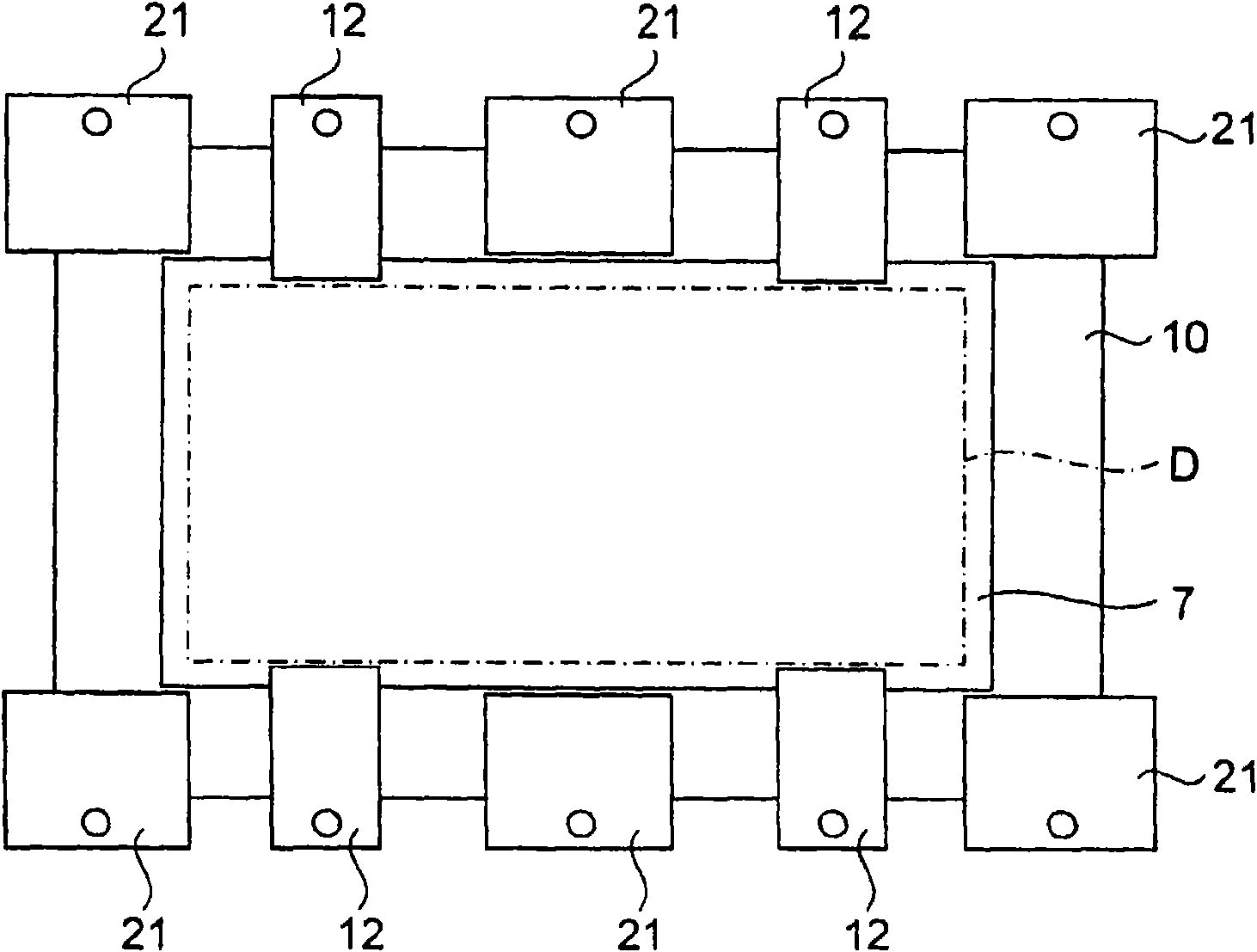
A display device has a light source (5), a diffusion plate (10) for diffusing light emitted from the light source, a support base (6) for supporting the diffusion plate, an optical sheet (7) placed onthe diffusion plate, a diffusion plate retainer (21) attached to the support base and holding the diffusion plate between itself and the support base by pressing the diffusion plate while avoiding the optical sheet, and a display panel (2) facing the diffusion plate. A warp of the diffusion plate (10) due to a temperature rise can be suppressed by pressing the diffusion plate (10) by using the highly rigid diffusion plate retainer (21). Because the optical sheet (7) is not pressed by the diffusion plate retainer (21), the optical sheet (7) can be placed so as to be able to expand and retract.Therefore, wrinkles in the optical sheet due to a temperature rise can be prevented. Consequently, even if the diffusion plate (10) is increased in size, an excellent display image can be obtained.

Description

technical field [0001] The present invention relates to a display device and a television receiver including a diffuser plate facing a display panel such as a liquid crystal panel. Background technique [0002] Patent Document 1 discloses a display device such as a conventional television receiver. In this display device, an illuminating device is arranged on the rear side of a display panel such as a liquid crystal panel. The lighting device has a light source supported by a base and a diffusion plate. The diffusion plate is disposed opposite to the display panel, and diffuses light emitted from the light source disposed on the rear side to guide it to the display panel. [0003] An optical sheet such as a lens sheet or a prism sheet is provided on the emission side of the diffusion plate. The diffusion plate and the optical sheet are fixed by sandwiching the surrounding parts between the pressing member attached to the base plate and the base plate. Thereby, the diffus...

Claims


Application Information

Patent Timeline
Patent Type & Authority Applications(China)
IPC IPC(8): G02F1/13357F21S2/00F21V17/00H04N5/66
CPCG02F2201/46H04N5/66G02F1/133308G02F1/133608G02F2201/54G02F2001/133607H04N5/64G02F1/133606G02F2001/133317G02F1/133317G02F1/133607
Inventor 黑水泰守
Owner SHARP KK
Learn More