
Lifetime extending and performance improvements of micro-structured fibres via high temperature loading

A microstructure and fiber technology, applied in the direction of microstructure optical fiber, cladding optical fiber, nonlinear optics, etc., can solve problems such as fiber damage and system catastrophic failure, and achieve the effect of prolonging the working life

Inactive Publication Date: 2010-03-24
KOHERAS
View PDF0 Cites 8 Cited by
  • Summary
  • Abstract
  • Description
  • Claims
  • Application Information

AI Technical Summary

Problems solved by technology

If the peak power or pulse energy exceeds the glass block or glass-air interface damage threshold, the input face or first few millimeters of the fiber may be destroyed and the system will fail catastrophically

Method used


Image

  • Lifetime extending and performance improvements of micro-structured fibres via high temperature loading
  • Lifetime extending and performance improvements of micro-structured fibres via high temperature loading
  • Lifetime extending and performance improvements of micro-structured fibres via high temperature loading

Examples


Embodiment Construction

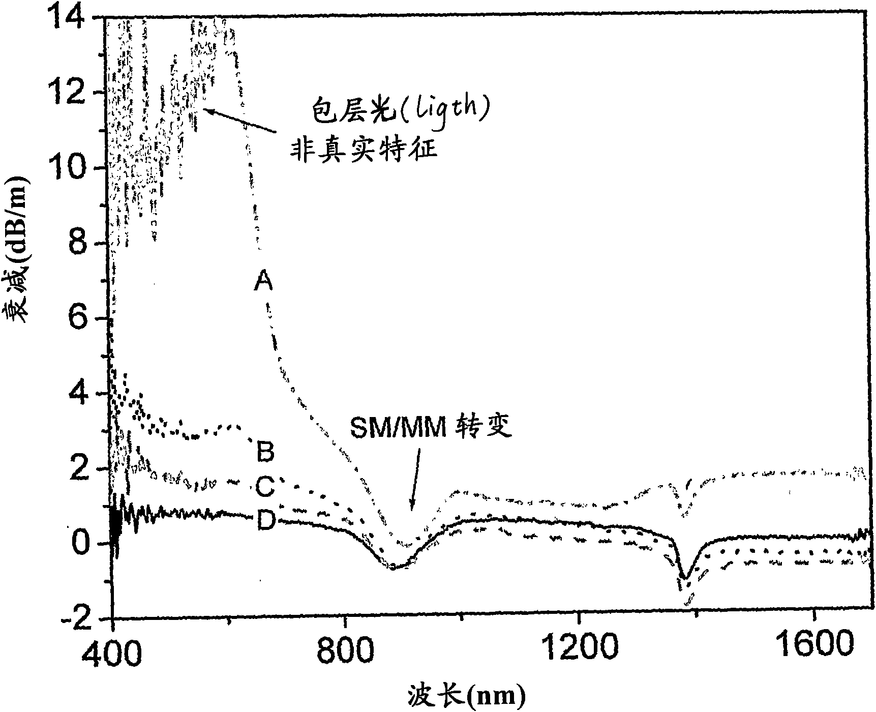
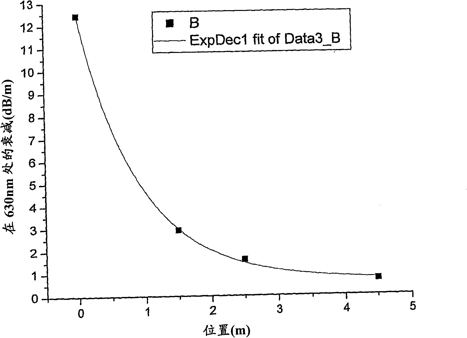
[0053] In the following the invention will be discussed based on the measured data. The conclusions drawn from these should not be considered as limiting to the specific cases of the experiments below, but rather as illustrations of the results obtainable by the present invention.

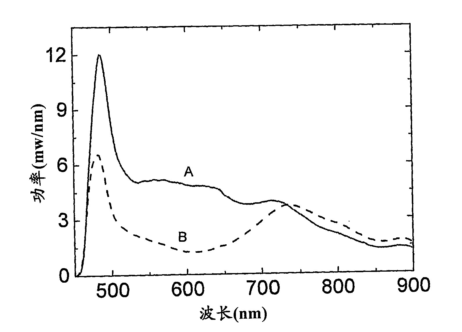
[0054] The data measured below were obtained for a supercontinuum light source comprising a pump source and a nonlinear microstructured silica fiber. The fiber was pumped at 1064nm with 8ps pulses at a repetition rate of 80MHz providing 15W input average power (23kW peak power). The fibers have a mode field diameter of 3.5 μm and are approximately 7 meters in length.

[0055] It is preferred that the length of the fiber be kept short to keep consumption of the fiber to a minimum while still providing sufficient length to allow the nonlinear processes underlying the supercontinuum to provide the desired spectrum. This length usually depends on the shape of the pulse, since shorter fibers are usual...


PUM

PropertyMeasurementUnit
diameteraaaaaaaaaa

Abstract

The invention relates to an optical fibre comprising a core and a cladding comprising a core material and a cladding material, respectively, wherein said fibre is a non-linear microstructured opticalfibre, said microstructured optical fibre being obtainable by a method comprising loading said core material and optionally said cladding material with hydrogen and / or deuterium whereby the lifetime of the fibre may be extended in high pulse applications.

Description

technical field [0001] The invention relates in particular to an optical fiber comprising a core and a cladding, each comprising a core material and a cladding material respectively, wherein said fiber is of the nonlinear microstructured optical type. Background technique [0002] More recently, optical fibers known as microstructured fibers, photonic crystal fibers (PCFs) or holey fibers have been developed (a special case of such fibers is sometimes called a photonic bandgap fiber (PBG)). This PCF consists of a cladding made of a transparent material in which an array of holes is embedded along the length of the fiber [J.C.Knight et al., Opt.Lett.21 (1996) p.1547. Errata: Opt.Lett.22 (1997) p.484 ]. These holes are typically arranged laterally in a periodic array and filled with a material having a lower refractive index than the remainder of the cladding. The center of the fiber usually includes periodic transparent regions interrupting the cladding, which often functio...

Claims


Application Information

Patent Timeline
Patent Type & Authority Applications(China)
IPC IPC(8): G02F1/365
CPCG02F1/365G02F2001/3528G02B6/02295G02F1/3528
Inventor C·L·汤姆森
Owner KOHERAS
Learn More