Battery charger circuit operated from a three-phase network

A battery charger, electrolytic capacitor technology, applied in battery circuit devices, current collectors, circuit devices, etc., to achieve the effect of small size

Inactive Publication Date: 2010-03-24
安德拉斯·法扎卡斯
View PDF3 Cites 1 Cited by
  • Summary
  • Abstract
  • Description
  • Claims
  • Application Information

AI Technical Summary

Problems solved by technology

In view of the very strong current pulses present in operation, the insertion of additional capacitors can only be ac

Method used


Image

  • Battery charger circuit operated from a three-phase network
  • Battery charger circuit operated from a three-phase network

Examples


Embodiment Construction

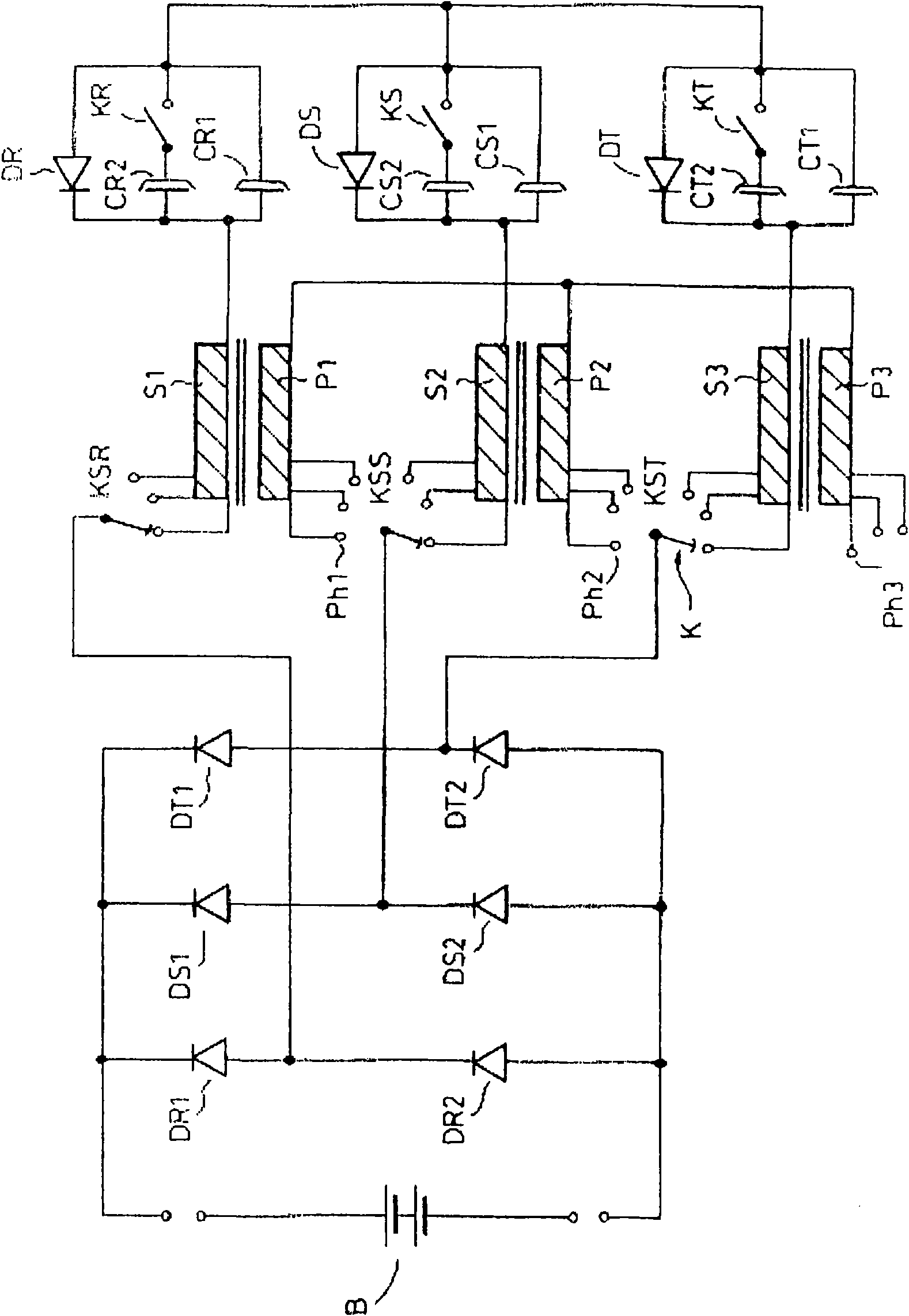
[0016] figure 1 The battery charger circuit shown includes a three-phase transformer with primary windings P1 , P2 and P3 and secondary windings S1 , S2 and S3 . The primary windings P1 , P2 , P3 are connected in a star circuit and coupled to the phase lines Ph1 , Ph2 , Ph3 of the three-phase mains network. In order to regulate the secondary voltage, the secondary windings S1 , S2 , S3 each have a plurality of tap terminals coupled to a multipole switch K, the poles having a common control moving element. The switch K comprises moving contacts KSR, KSS, KST corresponding to the three phase lines R, S, T of the mains network. The moving contact KSR associated with the phase line R is connected to the common line of the series diodes DR1 and DR2, the moving contact KSS is coupled to the common line of the series diodes DS1 and DS2, and finally the moving contact KST is coupled to the series connection of the series diodes DT1 and DS2. Common line for DT2. The respective other...


PUM

PropertyMeasurementUnit
Capacitanceaaaaaaaaaa

Abstract

Battery charger circuit operated from a three-phase network, comprises a three phase mains transformer with three secondary windings and three parallel connected pairs of series diodes, wherein the central interconnection lines of each of the series pairs of diodes are connected to respective end terminals of an associated one of the three secondary windings of the transformer, and the battery charger circuit comprises three similar circuits each of them is associated with a respective phase, each of the similar circuits comprises a permanently connected electrolytic capacitor (CR1, CS1, CT1)and a diode (DR, DS, DT) in parallel with the capacitor, wherein one end of the similar circuits is connected to the other terminal of the secondary winding (S1, S2, S3) of the associated phase, and the other ends of the similar circuits are interconnected.

Description

technical field [0001] The invention relates to a battery charger circuit operated from a three-phase network comprising a three-phase mains transformer with three secondary windings and three parallel connected series diode pairs, wherein the intermediate interconnection of each series diode pair The wires are connected to respective end terminals of an associated one of the three secondary windings of the transformer. Background technique [0002] Charging of batteries with higher storage capacities is generally addressed by using the available three-phase mains power supply, several types of three-phase battery chargers are commercially available. In a conventional solution, the output terminals of the secondary phase windings of the three-phase transformer are coupled to the corresponding bridge rectifiers, which can be connected in parallel on their DC side, i.e. by interconnection of their DC output terminals, thus obtaining The DC voltage is used to power conventiona...

Claims


Application Information

Patent Timeline
IPC IPC(8): H02J7/02
CPCH02J7/022H02J7/02H02J2207/20H02J7/04
Inventor 安德拉斯·法扎卡斯
Owner 安德拉斯·法扎卡斯
Why Eureka
Try Eureka