Electric power source control device and heat pump device using the electric power source control device
A technology of power supply control device and control circuit, which is applied in the direction of high-efficiency power electronic conversion, output power conversion device, electrical components, etc., can solve problems such as current sensor inability to cope with device failure, etc.
- Summary
- Abstract
- Description
- Claims
- Application Information
AI Technical Summary
Problems solved by technology
Method used
Image
Examples
Embodiment approach 1
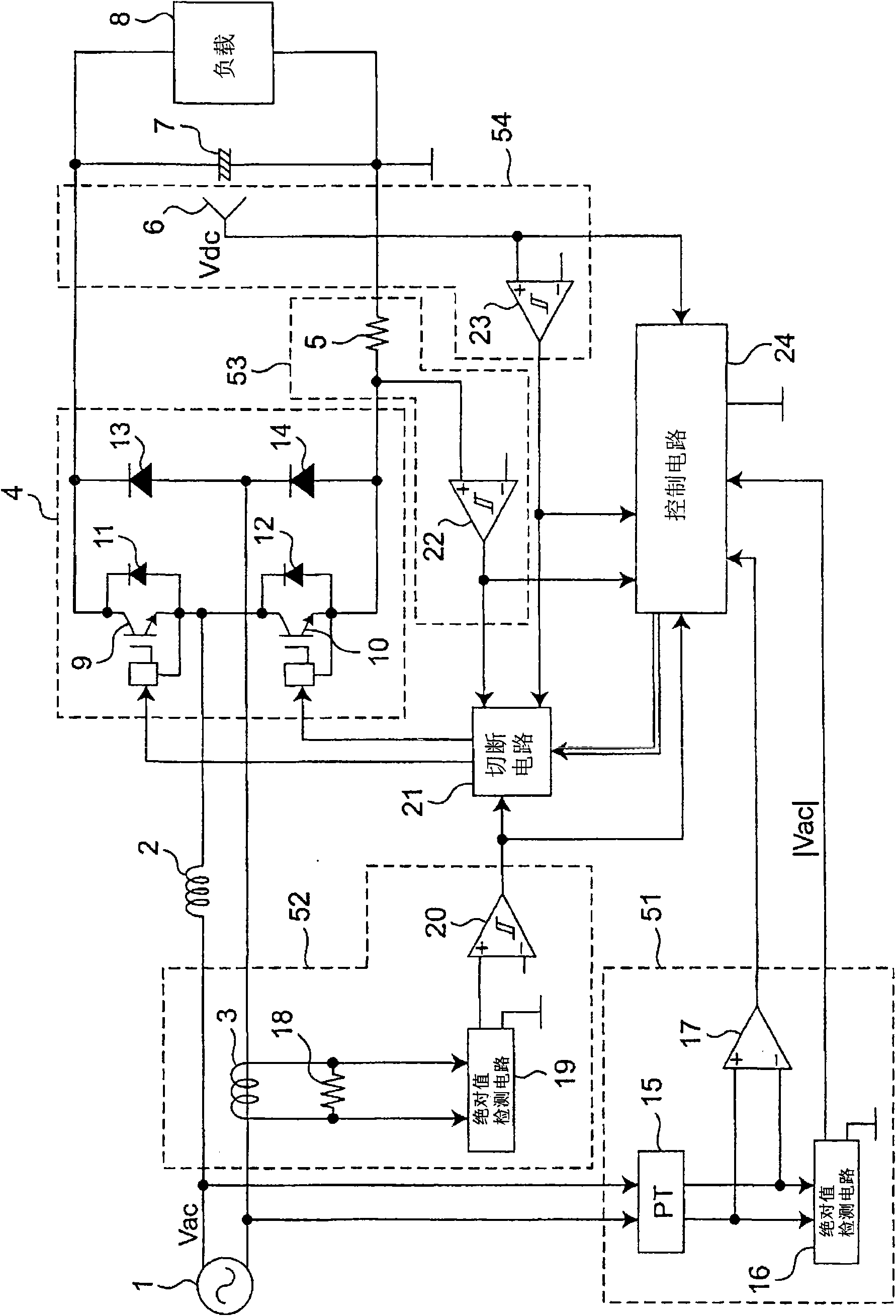
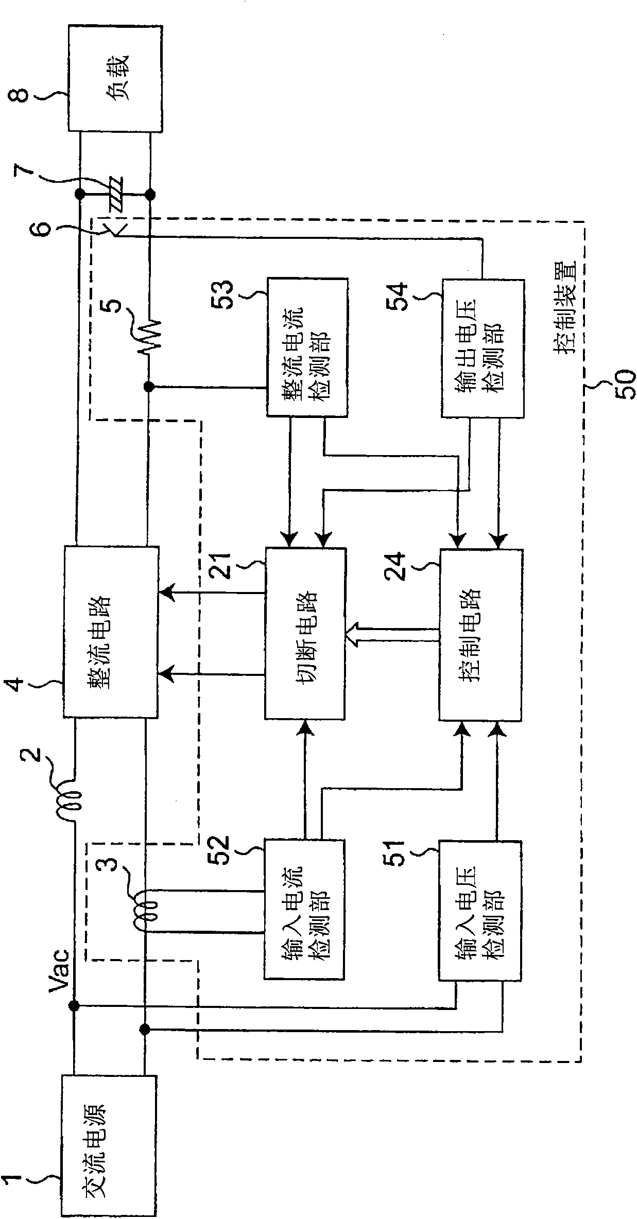
[0054] figure 1 It is a circuit diagram showing the configuration of the power supply control device according to Embodiment 1 of the present invention with a part of blocks. figure 2 It is a block diagram showing the configuration of the power supply control device according to the first embodiment.
[0055] figure 1 In the power control device according to Embodiment 1, the AC power supply 1 is connected to the full-wave rectification circuit 4 as a rectification circuit through the reactor 2, and the AC power supply 1, the reactor 2 and the full-wave rectification circuit 4 form a closed loop. The full-wave rectification circuit 4 is composed of two switching elements (IGBTs) 9 and 10 and four diodes 11 , 12 , 13 and 14 . The first switching element 9 and the second switching element 10 are connected in series, and one end of the reactor 2 is connected to the connection point thereof. The other end of the reactor 2 is connected to an output end of the AC power source ...
Embodiment approach 2
[0101] Next, use Figure 5 as well as Image 6 , the power supply control device according to Embodiment 2 of the present invention will be described. Figure 5 It is a circuit diagram showing the configuration of the power supply control device according to Embodiment 2 with a part of blocks. Image 6 It is a waveform diagram showing input current and rectified current in the power supply control device according to the second embodiment. In the power supply control device of Embodiment 2, the difference from the power supply control device of Embodiment 1 above is that the rectified current flowing from the full-wave rectification circuit 4 to the smoothing capacitor 7 is detected by the resistor 5, and the detected current value is expressed as The rectified current information is input to the control circuit 24 through the sample hold circuit 25 . Therefore, in the description of Embodiment 2 and Figure 5 Herein, the components having the same functions and structures...
Embodiment approach 3
[0109] Next, use the attached Figure 7 A power supply control device and a heat pump device according to Embodiment 3 of the present invention will be described. Figure 7It is a circuit diagram showing the configuration of the power supply control device according to Embodiment 3 with a part of blocks. The power control device of Embodiment 3 differs from the power control device of Embodiment 2 in that a smoothing circuit 26 is further provided, and the output of the second absolute value detection circuit 19 is smoothed in the smoothing circuit 26. (take the average value), and input the average value information to the control circuit 24. In this way, in the power supply control device according to Embodiment 3, after the signal indicating the absolute value of the output of the current converter 3 is input to the smoothing circuit 26 and smoothed, the average value of the input current is detected. The detected average value information of the input current is input to...
PUM
 Abstract
Description
Claims
Application Information
 - R&D
- Intellectual Property
- Life Sciences
- Materials
- Tech Scout
- Unparalleled Data Quality
- Higher Quality Content
- 60% Fewer Hallucinations
Browse by: Latest US Patents, China's latest patents, Technical Efficacy Thesaurus, Application Domain, Technology Topic, Popular Technical Reports.
© 2025 PatSnap. All rights reserved.Legal|Privacy policy|Modern Slavery Act Transparency Statement|Sitemap|About US| Contact US: help@patsnap.com


