Hollow fiber membrane dehumidifier

A silk membrane and hollow technology, which is applied in the field of hollow fiber membrane dehumidification devices, can solve problems such as difficult configuration, uneven flow of waste gas or purified gas, and increased area, so as to improve assembly and operability, shorten assembly time and disassembly the effect of time

Inactive Publication Date: 2010-03-31
KK TOSHIBA
View PDF1 Cites 5 Cited by
  • Summary
  • Abstract
  • Description
  • Claims
  • Application Information

AI Technical Summary

Problems solved by technology

[0015] Therefore, there is a problem that when inserting the hollow fiber membrane module 1 into the main body casing 6, it is difficult to insert the third sealing member 18 and the fourth sealing member 19 that are not fixed to the hollow fiber membrane module 1 without falling off. When the hollow fiber membrane module 1 is pulled out or replaced, it may fall into the main body casing 6
There is a problem that the area occupied by one hollow fiber membrane module 1 increases due to the outer diameter of the cap 15, and the main body case 6 becomes larger.
[0017] Moreover, since the hollow fiber membrane module 1 has a vertically long structure, there is a problem in the conventional holding method that the third sealing member 18, the fourth sealing member 19, and the second sealing member installed on the upper head 11 and the lower head 20 will It is very difficult to configure five seals 22 on concentric circles
In this way, since the exhaust gas inlet chamber 7, the exhaust gas treatment chamber 8, the purified gas chamber 9, and the exhaust gas outlet chamber 10 are composed of one chamber, there is a problem that the exhaust gas or the purified gas flowing through the hollow fiber membrane module 1 is generated depending on the flow rate of the exhaust gas. Uneven flow, reduced dehumidification performance
[0019] Furthermore, in the conventional hollow fiber membrane dehumidifier 2, there is a problem that the directions of the purge gas inlet 14 and the purge gas outlet 29 of the hollow fiber membrane module 1 are arbitrary relative to the directions of the purge gas inlet 28 and the purge gas outflow 30. It is determined that the exhaust gas and purified gas flowing in the hollow fiber membrane module 1 are not uniform, and the dehumidification performance is reduced.

Method used


Image

  • Hollow fiber membrane dehumidifier
  • Hollow fiber membrane dehumidifier
  • Hollow fiber membrane dehumidifier

Examples


Embodiment Construction

[0036] Hereinafter, embodiments of the hollow fiber membrane dehumidification device of the present invention will be described with reference to the drawings. Here, the same symbols are attached to the same or similar parts, and repeated explanations are omitted.

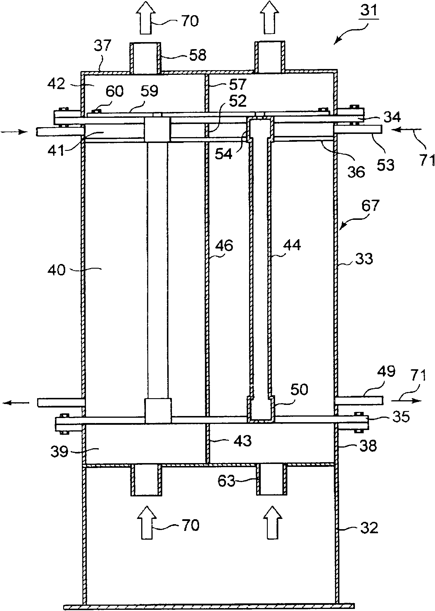
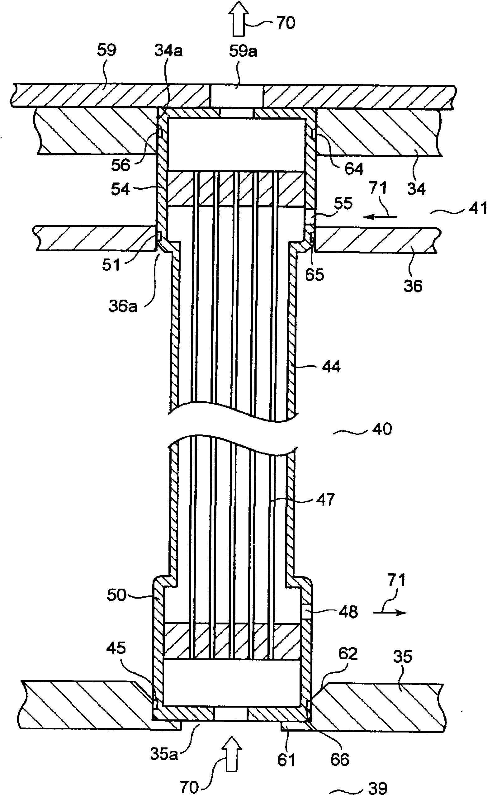
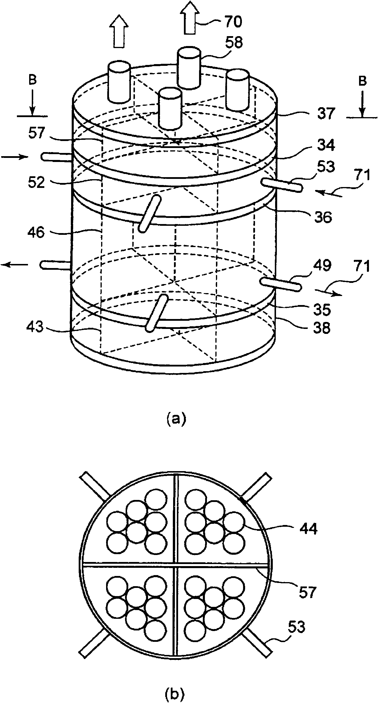
[0037] figure 1 It is a schematic longitudinal sectional view showing the structure of the hollow fiber membrane dehumidifier according to the first embodiment of the present invention, figure 2 yes means figure 1 A partial enlarged view of the installation structure of the hollow fiber membrane module shown, image 3 yes means figure 1 (a) is a perspective view of the hollow fiber membrane dehumidifier, (b) is a cross-sectional view cut along the B-B direction of (a).

[0038] First, as an example, using figure 1 The basic configuration of the hollow fiber membrane dehumidification device 31 suitable for dehumidification of exhaust gas from a nuclear power plant will be described.

[0039] Such as fig...


PUM


Abstract

Assembling performance, handling performance, sealing performance, and dehumidification performance of a hollow fiber membrane module are enhanced while achieving downsizing of a hollow fiber membranedehumidifier. The hollow fiber membrane dehumidifier includes a dehumidification container (67) composed of a lower trunk (38) provided with an exhaust gas inlet (63), an upper trunk (37) provided with an exhaust gas outlet (58), and a body trunk (33); a lower tube sheet (35) for constructing an exhaust gas inlet chamber (39) in the body trunk (33); an upper tube sheet (34) for constructing an exhaust gas outlet chamber (42) in the body trunk (33); a partition plate (36) for partitioning the interior of the body trunk (33) to an exhaust gas processing chamber (40) and a purge gas chamber (41); a plurality of hollow fiber membrane modules (44) inserted into each through hole of an upper tube sheet (34), the partition plate (36), and the lower tube sheet (35); and a sealing material held inthe sealing groove formed in the hollow fiber membrane module (44) for sealing among an upper head (54), a lower head (50), the upper tube sheet (34), the partition plate (36), and the lower tube sheet (35).

Description

technical field [0001] The present invention relates to a hollow fiber membrane dehumidification device for removing moisture contained in radioactive gas waste (hereinafter referred to as waste gas) generated in a nuclear power plant by using a hollow fiber membrane module. Background technique [0002] Conventionally, a hollow fiber membrane dehumidification device incorporating a dehumidifying hollow fiber membrane is known as a device for selectively separating and removing moisture from humid air to obtain dry air (for example, refer to Patent Document 1). [0003] Generally, the dehumidification hollow fiber membrane is processed into a hollow fiber membrane with an outer diameter of about 0.3mm and high water vapor permeability; The ends are fixed to form a hollow fiber membrane module. [0004] The hollow fiber membrane module is filled with multiple hollow fiber membrane dehumidifiers, and the difference in mole fraction inside and outside the membrane is caused by...

Claims


Application Information

Patent Timeline
Patent Type & Authority Applications(China)
IPC IPC(8): B01D53/26B01D53/22B01D63/02B01D69/08G21F9/02
CPCB01D2313/06B01D63/043B01D2313/04B01D63/021G21F9/02B01D53/268
Inventor 关口晃一
Owner KK TOSHIBA
Why Eureka
Try Eureka