Vehicle
A vehicle and body technology, applied in the field of vehicles, can solve problems such as bad riding
- Summary
- Abstract
- Description
- Claims
- Application Information
AI Technical Summary
Problems solved by technology
Method used
Image
Examples
no. 2 Embodiment approach
[0235] In the first embodiment, through the passenger's acceleration feeling coefficient C Sense A preset value is assigned such that the ratio of the perceived acceleration to the acceleration (target value) of the vehicle is constant.
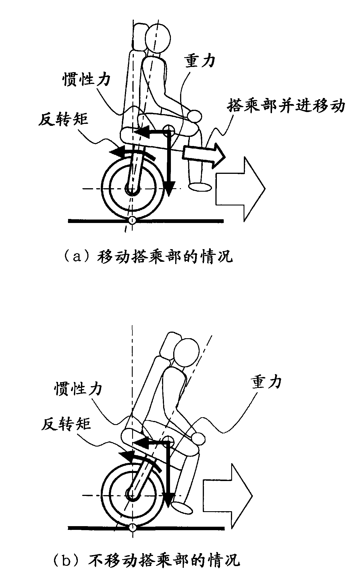
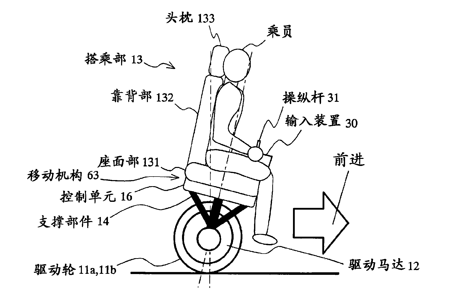
[0236] Correspondingly, in the second embodiment, the degree of somatosensory acceleration can be quantitatively adjusted according to the passenger's preference. That is, when determining the target vehicle body attitude, the inclination angle of the vehicle body and the movement amount of the riding part are determined according to the passenger's preference, so as to adjust the degree of somatosensory acceleration. For example, if a strong acceleration feeling is desired, the boarding portion 13 is moved while suppressing the inclination of the vehicle body. Moreover, by making the occupant's acceleration feeling coefficient C in formula 2 Sense Variable, to achieve the above purpose.
[0237] In this way, by changing the passenger's ac...
Deformed example 2
[0415] (b) Modification 2... Estimation by observer
[0416] In Modification 1 above, it was explained that the mass m of the boarding part is calculated using the formula 26 based on the actual measurement value of the load meter. S (and car body mass m 1 ), but in this Modification 2, using the moving state λ based on the boarding part S or balancer thrust S B Etc. observer, estimated ride mass m S value.
[0417] The main control ECU 21 estimates the boarding part mass m using the boarding part movement model of the following formula 28 S . g is the acceleration due to gravity, C S is the viscous coefficient of friction relative to the movement of the seat. Also, by differentiating the velocity [x], the acceleration [[x]] of each state quantity x is obtained.
[0418] In Equation 28, for example, the thrust S required to move the seat S The larger the value, the estimated ride mass m S bigger.
[0419] Formula 28
[0420] m S =(S S -D S [λ S ]) / ([[λ S ]]+λ ...
no. 7 Embodiment approach
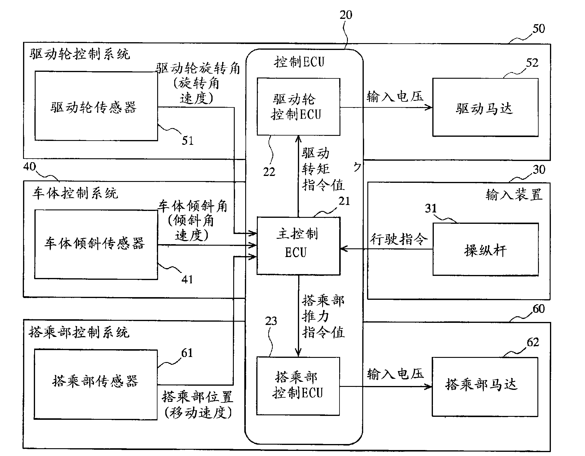
[0583] In the seventh embodiment, the drive motor 52 and the movement of the boarding part are used in distinction according to the frequency component of the disturbance. Specifically, in the feedback control, the low-frequency component of the deviation is associated with the movement of the boarding part, and the high-frequency component is associated with the drive motor 52, thereby suppressing the vibration due to the disturbance.
[0584] When the movement of the boarding portion 13 is used for posture control of the vehicle body, high-frequency vibrations may be generated, which may affect the ride quality. This is because there is a "lag" in the body attitude control based on the movement of the boarding part, and it is not suitable for fine control.
[0585] Also, if falling into a state of equilibrium with a posture different from the target posture, for example, the vehicle body may remain in a state in which the vehicle body is tilted more than the target angle and...
PUM
 Abstract
Description
Claims
Application Information
 - R&D
- Intellectual Property
- Life Sciences
- Materials
- Tech Scout
- Unparalleled Data Quality
- Higher Quality Content
- 60% Fewer Hallucinations
Browse by: Latest US Patents, China's latest patents, Technical Efficacy Thesaurus, Application Domain, Technology Topic, Popular Technical Reports.
© 2025 PatSnap. All rights reserved.Legal|Privacy policy|Modern Slavery Act Transparency Statement|Sitemap|About US| Contact US: help@patsnap.com


