Ring for fluid production dispensing

A technology of fluid products and valves, which is applied in the ring field of aerosol dispensing valves, and can solve problems such as high manufacturing costs, manufacturing tolerances, and complex shapes

Inactive Publication Date: 2010-03-31
APTAR FRANCE SAS
View PDF0 Cites 2 Cited by
  • Summary
  • Abstract
  • Description
  • Claims
  • Application Information

AI Technical Summary

Problems solved by technology

However, the shape of these rings is quite complicated, so the manufacturing cost is relatively high
The other rings are held in the reservoir by compression sleeves, which further complicates assembly, especially due to manufacturing tolerances

Method used


Image

  • Ring for fluid production dispensing
  • Ring for fluid production dispensing
  • Ring for fluid production dispensing

Examples


Embodiment Construction

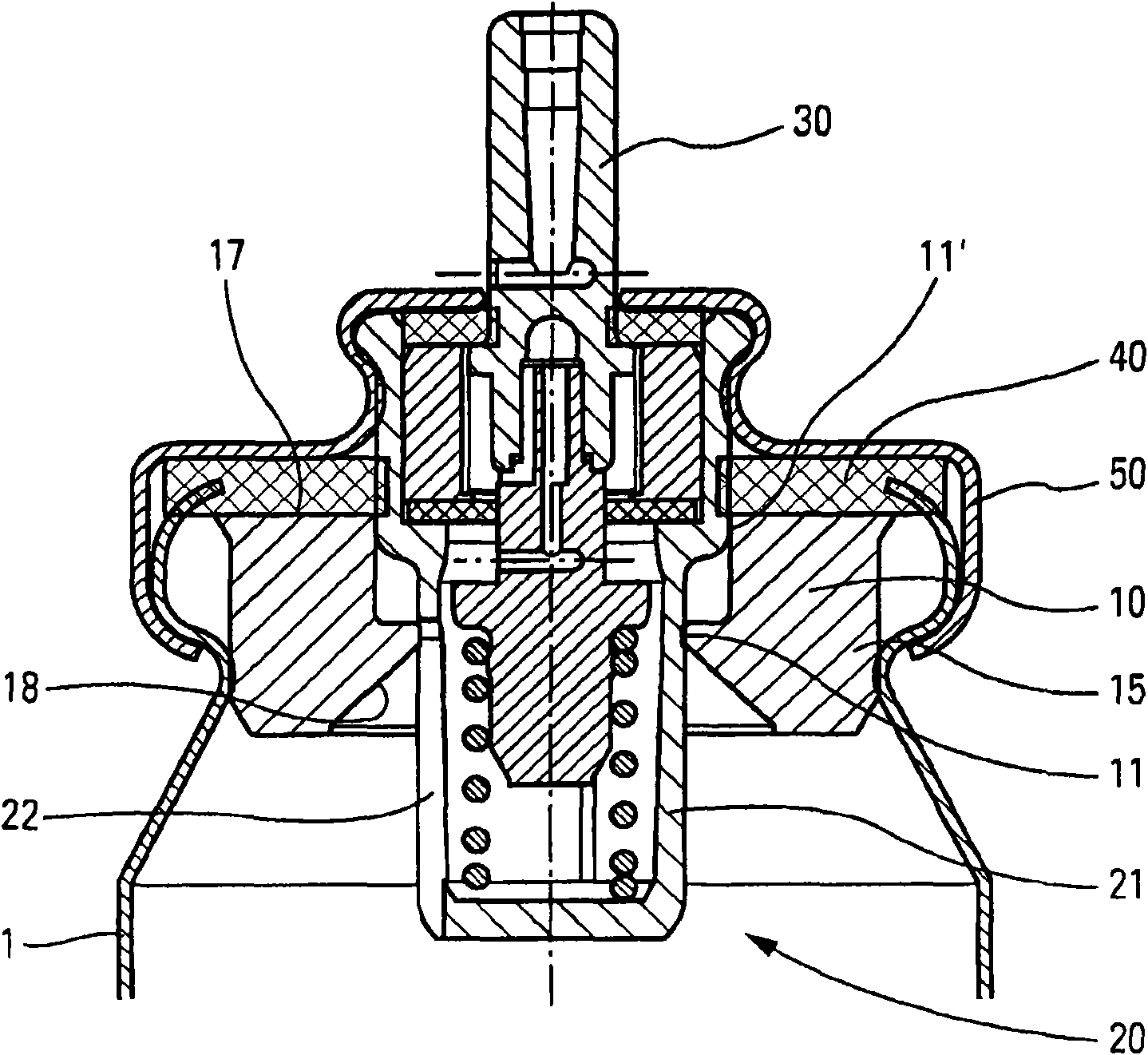
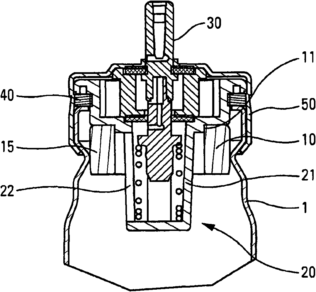
[0027] [27] Referring to the figures, the aerosol device comprises a reservoir 1 containing the product to be dispensed. The product may be of the pharmaceutical type and an actuation gas may be provided to dispense the product through an aerosol valve 20, preferably a dose valve. The aerosol valve includes a valve body 21 , and a valve element 30 slides in the valve body 21 . The valve body 21 is assembled on the neck of the reservoir 1 by means of a fixing ring or cap 50, in particular of the insertable type, with a neck gasket 40 interposed therebetween for sealing. The valve shown is particularly intended for use in an inverted position, ie the valve is located below the reservoir when a dose is expelled. The valve body 21 includes one or more openings 22 allowing the valve to be filled with product from a reservoir. The shape of said opening is shown as a longitudinal side slit 22 extending over part of the height of the valve body 21 . As a variant, one or more openin...


PUM


Abstract

The invention relates to a ring (10) to be provided about a valve body (21) of an aerosol dispensing valve (20) mounted via a securing member (50) such as a crimped cap, on a tank containing a productto be dispensed, wherein said ring (10) includes at least one inner portion (11, 11) interacting with said valve body (21), and an outer portion (15), said ring (10) being made of a substantially rigid single piece, and said outer portion (15) being adapted for sealed interaction by material deformation with a portion of the tank (1) upon the assembly of the securing member (50) on the tank (1).

Description

technical field [0001] [01] The present invention relates to rings for aerosol dispensing valves. Background technique [0002] [02] It is known to use rings in conjunction with aerosol dispensing valves, in particular dosing valves mounted on a reservoir containing the product to be dispensed. These rings are used in particular in valves which can be used in an inverted position, ie the valve is located below the reservoir when a dose of product is expelled. These rings generally have two main functions, namely, on the one hand, to ensure the maximum quantity of product contained in the dispensing reservoir, and at the same time to limit the dead volume below the valve inlet when the valve is in the inverted use position. On the other hand, the ring also serves to limit the contact of the product with the neck gasket, which is generally located between the neck of the reservoir and the retaining ring or cap used to secure the valve to the container. By limiting the contac...

Claims


Application Information

Patent Timeline
Patent Type & Authority Applications(China)
IPC IPC(8): B65D83/14
CPCB65D83/38B65D83/54B65D83/36
Inventor C·玛丽I·弗莱彻
Owner APTAR FRANCE SAS
Why Eureka
Try Eureka