Lifting device used on rubbish compression machine (station)

A garbage compressor and garbage technology, which is applied in the direction of garbage transmission, garbage collection, storage devices, etc., can solve the problems of increasing space height, inconvenient maintenance of oil cylinders, complex structure, etc., and achieve stable operation, convenient maintenance and installation, and remarkable results

Inactive Publication Date: 2010-04-07
吉林前沅专用汽车制造股份有限公司
View PDF2 Cites 8 Cited by
  • Summary
  • Abstract
  • Description
  • Claims
  • Application Information

AI Technical Summary

Problems solved by technology

The disadvantages of this lifting device are: first, it is inconvenient to maintain the oil cylinder in the pit; height, no room for lower height
[0003] There is a Chinese patent number ZL200420068109.0 for the lifting device of the garbage compression station, and the authorized announcement number is CN2707731Y. The Synchronous Lifting Device for Garbage Compression Station consists of a lifting cylinder horizontally fixed at one end of the supporting frame, and the steel wire rope fixed on its head is driven by the expansion and contraction of the piston, so that the steel wire rope surrounds the fixed pulleys fixed at the four corners of the frame, and will be tied to the other end of the rope. The lifting hook and its box at one end are lifted or lowered, and the lifting height and the piston stroke are also 1:1. The disadvantage of this lifting device is that it is fixed on the top of the four columns, which increases the height of the space itself, so it is especially suitable. It is used in occasions where the lifting height does not exceed 3 meters

Method used


Image

  • Lifting device used on rubbish compression machine (station)
  • Lifting device used on rubbish compression machine (station)
  • Lifting device used on rubbish compression machine (station)

Examples


Embodiment 1

[0017] Embodiment 1: see Figure 1-Figure 4

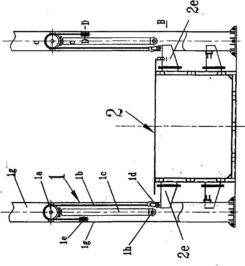
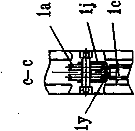
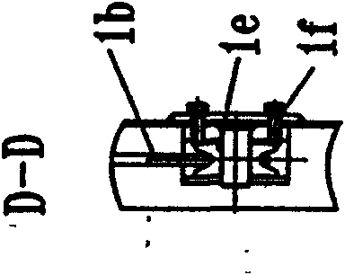
[0018] A lifting device used on a garbage compressor, including a garbage compressor and a lifting device, is characterized in that: a cantilever beam 2e is fixed on the garbage volume box 2 of the garbage compressor; the lifting device 1 is composed of a column 1g , an oil cylinder lifting mechanism, and a pulley and sliding rope transmission mechanism; the four columns are arranged on both sides of the garbage bin, and their cross-sections are concave-shaped and hollow with openings, which are formed by pressing steel plates, and the cavities are respectively disposed from the opening Enter the oil cylinder lifting mechanism and the pulley sliding rope transmission mechanism; the described oil cylinder lifting mechanism is composed of the lifting cylinder 1c, the piston 1y, the transmission pulley seat 1j fixed on the top of the piston, and the oil cylinder seat 1h fixed on the lower end of the oil cylinder, wherein the oil cylin...

Embodiment 2

[0020] Example 2: see Figure 5

[0021] A lifting device used on a garbage compression station, including a garbage compression station and a lifting device. The difference between this lifting device and Embodiment 1 is that the lifting lug 2g is fixed on the cantilever beam 2e of the garbage volume box 2, The end of the sliding rope 1b is hinged on the suspension hook 2L with a rope clamp 1d, and the suspension hook is connected with the lifting lug.

[0022] The working principle of this lifting device is: the oil cylinder lifting mechanism drives the pulley and the sliding rope transmission mechanism drives the garbage volume box to lift; during work, the load-bearing pulley only bears the load and its position is fixed. When the lifting cylinder is lifted by one meter, the transmission pulley on the top of the piston Thereupon one meter rises, because the sliding rope on the driving pulley is fixed around or hinged at one end in the load-bearing pulley, so the other end...


PUM


Abstract

The invention particularly relates to a lifting device used on a rubbish compression machine (station), which comprises a lifting device 1 and a rubbish volume box 2, and is characterized in that: a cantilever beam 2e is fixed on the rubbish volume box 2; the lifting device 1 comprises a stand column 1g, an oil cylinder lifting mechanism, a pulley and sliding rope transmission gear; the cross section of the stand column 1g is in a sunken shape and hollow and provided with an opening, and the oil cylinder lifting device and the pulley and sliding rope transmission gear are arranged in the stand column 1g; the lifting mechanism consists of a lifting oil cylinder 1c, a piston 1y, a pulley base 1j and an oil cylinder base 1h, the pulley and sliding rope transmission gear is composed of a driven pulley 1a, a sliding rope 1b, a bearing pulley 1e and a bearing support 1f; the middle of the sliding rope is wound in a bearing pulley, two sides are wound on the driven pulley, two ends are hinged on the cantilever beam 2e by a rope clip 1d. The lifting height and lifting speed of the invention is twice as that of the oil cylinder, the height of the stand column and factory buildings is reduced by more than 15%, the structure is simple and the efficiency is high.

Description

Technical field: [0001] The invention belongs to the technical field of urban environmental sanitation equipment, and in particular relates to a lifting device used on a garbage compressor or a garbage compression station. Background technique: [0002] At present, Chinese patent application number 200810062297.9 and publication number CN10298195A are used for lifting devices of garbage compressors, which disclose a kind of "buried garbage compressor" composed of garbage bins, compression mechanisms, push-out mechanisms and lifting devices. Its lifting The device uses a lifting cylinder to realize the rising or falling of the garbage box. The lifting cylinder is installed on the foundation of the pit, and the end of the oil cylinder is pinned to the lifting seat to drive the garbage box to lift. This structure determines that the lifting height of the box must be the same as that of the oil cylinder. The strokes are equal, that is, 1:1, and the height of the column must be a...

Claims


Application Information

Patent Timeline
Patent Type & Authority Applications(China)
IPC IPC(8): B65F9/00
Inventor 孙凤山隋德军张德喜杨永吉谢海瑞张伟杰王永吉
Owner 吉林前沅专用汽车制造股份有限公司
Why Eureka
Try Eureka