
Axial flow wind wheel with improved blades

A technology of axial flow wind and blades, which is applied to components of pumping devices for elastic fluids, non-variable pumps, pump components, etc., and can solve problems such as noise and efficiency deterioration, impeller efficiency reduction, and efficiency drop

Inactive Publication Date: 2010-04-07
GUANGDONG SUNWILL PRECISING PLASITC CO LTD
View PDF1 Cites 16 Cited by
  • Summary
  • Abstract
  • Description
  • Claims
  • Application Information

AI Technical Summary

Problems solved by technology

But in general, for this type of low-pressure axial flow fan, the pressure at the air outlet of the fan is small, the pressure difference between the windward side and the leeward side of the blade trailing edge is not high, and there is a low pressure on the windward side of the leading edge of the blade, causing the leading edge of the blade to face the wind. The pressure difference between the side and the leeward side is large, and the leakage vortex loss is large, which increases the noise of the fan and reduces the efficiency; at the same time, due to the influence of the low pressure on the leeward side when the impeller is running, the impact of the blade tip on the airflow will be generated. Strong air turbulence, further worsening noise and efficiency
In this patent, the turned-up part of the leading edge of the blade is small, and the tip of the blade is flat like the usual axial flow fan, which has no effective effect on suppressing the leakage vortex at the leading edge of the blade and the airflow disturbance at the tip of the blade.
At the same time, when the impeller is running, the airflow flows along the direction of divergence of the outer circumference of the rotating shaft. Since the bending width of the trailing edge is larger than that of the leading edge, the flow of the airflow is hindered. This phenomenon will lead to energy loss and improve the efficiency of the impeller. reduce

Method used


Image

  • Axial flow wind wheel with improved blades
  • Axial flow wind wheel with improved blades
  • Axial flow wind wheel with improved blades

Examples


Embodiment Construction

[0016] The present invention will be further described below in conjunction with the accompanying drawings.

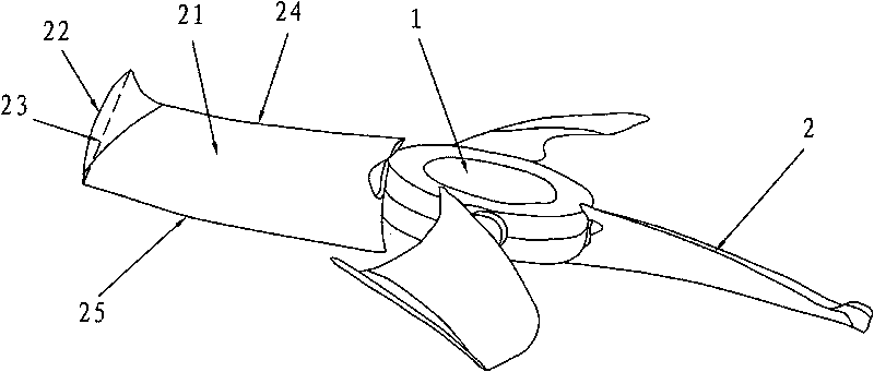
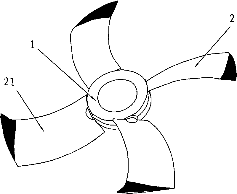
[0017] Such as figure 1 , figure 2 As shown, an axial-flow wind wheel with improved blades includes a hub 1 and blades 2, and the hub 1 and blades 2 are integrally formed. It gradually becomes smaller from the leading edge 24 to the trailing edge 25 . The overall shape of the blade 2 may not be changed, thereby controlling the leakage vortex at the leading edge of the outer circumference 22 and the air flow disturbance at the blade tip.

[0018] The maximum bending width is 20% of the distance from the hub 1 to the outer circumference 22 of the blade 2 .

[0019] The starting point of the bent portion is any position within the length of the 4 / 5 chord 23 from the outer circumference 22 of the blade 2 to the leading edge.

[0020] When the axial-flow wind wheel rotates, there is a lower pressure on the leeward side 21 of the leading edge 24 of the blade 1, resulti...


PUM


Abstract

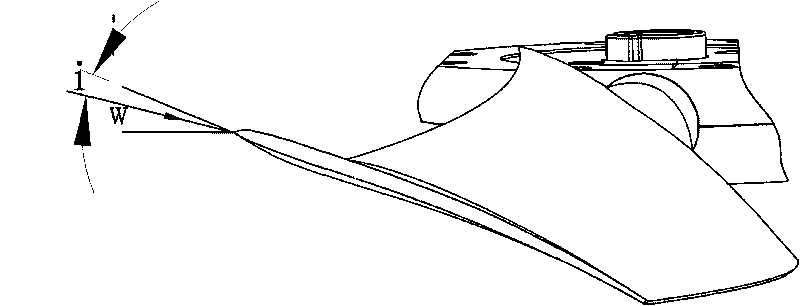
The invention discloses an axial flow wind wheel with improved blades, which comprises a wheel hub and a blade, and the blade and the wheel hub are formed as a whole. The invention is characterized in that the external circumferential part of the blade is bent from a windward side to a leeward side, and the bent width is gradually decreased from a front edge to a tailing edge; by adopting the structure, the leakage vortex at the external circumferential front edge and the air stream disturbance at the apex of the blade can be controlled. When the axial flow wind wheel rotates, the leeward side at the front edge of the blade has lower pressure, so as to cause large pressure difference between the windward side and the leeward side at the front edge of the blade, and turns up the apex of the blade towards the windward side, thus the pressure difference at the two sides of the apex of a blade can be reduced, and the leakage vortex at the external circumference of the blade can be inhibited. The angle that the air stream enters the front edge of the blade is greatly changed from the wheel hub to the external circumference, which can effectively reduce air-inlet impact loss, achieve the purpose of promoting the efficiency of the wind wheel; and meanwhile, when an impeller rotates, as the angle of attach of the air current i is smaller, the cutting air stream without impact at the front edge of the blade can generate lower pressure disturbance, thus playing an obvious role in reducing noise.

Description

technical field [0001] The invention relates to a blower, in particular to an axial-flow wind wheel of the blower. Background technique [0002] In low-pressure ventilation systems (such as outdoor units of air conditioners, environmental protection air conditioners, factory ventilation equipment, etc.), axial flow fan blades are mostly used as air supply components, and axial flow fans are usually used, such as Figure 6 shown. It consists of more than two blades and a cylindrical hub, and the outer circumference of the blades is flat in the radial direction. Due to the high pressure difference between the windward side and the leeward side of the blade, the axial flow fan with this structure generates a large pressure gradient and a strong leakage vortex on the outer circumference of the blade, resulting in an increase in noise and a decrease in efficiency of the axial flow fan. [0003] Chinese patent ZL03800551.4, invention name: air blower, improved the outer circumfer...

Claims


Application Information

Patent Timeline
IPC IPC(8): F04D29/32F04D29/38
Inventor 陈望明杨昕王军毛军祥
Owner GUANGDONG SUNWILL PRECISING PLASITC CO LTD
Learn More