
Two-dimensional metallic photonic crystal-based light guide plate with polarization function

A technology of metal photonic crystals and light guide plates, which is applied to optical elements, light guides, and light guides of lighting systems for changing the spectral characteristics of emitted light. It can solve the problem of multiple film structures, complex structures, increased panel thickness and cost, etc. Problems, to achieve the effect of improving integration, improving utilization, reducing thickness and cost

Active Publication Date: 2010-04-28
厦门市为纳光电科技有限公司
View PDF1 Cites 19 Cited by
  • Summary
  • Abstract
  • Description
  • Claims
  • Application Information

AI Technical Summary

Problems solved by technology

There are some obvious deficiencies in traditional TFT-LCD panels: first, the traditional absorbing polarizer that produces linear polarization will cause nearly 1 / 2 of the light absorption loss; second, in order to increase the light uniformity of the backlight module, an optical diffusion film and Various devices such as prism anti-reflection coating increase the thickness and cost of the panel
Such a structure can make the non-linearly polarized light in the light source be recycled repeatedly in the light guide plate, and finally emerge as TM linearly polarized light, which improves the optical efficiency and reduces the use of front polarizers in the liquid crystal panel. However, this The structure of the technology is complex, the film layer structure is more, and the one-dimensional micron grating can only be adjusted in one direction

Method used


Image

  • Two-dimensional metallic photonic crystal-based light guide plate with polarization function
  • Two-dimensional metallic photonic crystal-based light guide plate with polarization function
  • Two-dimensional metallic photonic crystal-based light guide plate with polarization function

Examples


Embodiment Construction

[0021] The embodiments of the present invention are described in detail below. This embodiment is implemented on the premise of the technical solution of the present invention, and detailed implementation methods and specific operating procedures are provided, but the protection scope of the present invention is not limited to the following implementation example.

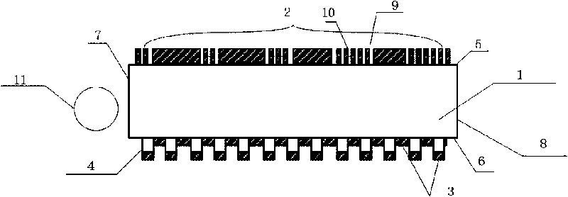
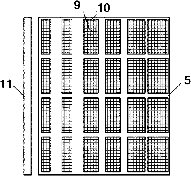
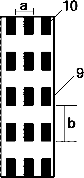
[0022] Such as figure 1 and figure 2 As shown, this embodiment includes: a light guide plate substrate 1, a metal photon array 2, a metal layer 3 and a one-dimensional grating 4, wherein: the metal photon array 2 is located on the light-emitting surface 5 of the light guide plate substrate 1, the metal layer 3 and the one-dimensional grating 4 are respectively located on the bottom surface 6 of the light guide plate base 1 opposite to the light exit surface 5 , and between the light exit surface 5 and the bottom surface 6 of the light guide plate base 1 are the light incident surface 7 and the side surface 8 resp...


PUM

PropertyMeasurementUnit
Heightaaaaaaaaaa
Heightaaaaaaaaaa
Cycleaaaaaaaaaa

Abstract

The invention discloses a two-dimensional metallic photonic crystal-based light guide plate with a polarization function, which comprises a light guide plate substrate, a metallic photonic array, a metal layer and a one-dimensional grating, wherein the metallic photonic array is positioned on a light emitting surface of the light guide substrate; the metal layer and the one-dimensional grating are respectively positioned on the bottom surface of the light guide substrate opposite to the light emitting surface; and an light incidence surface and a side surface are positioned between the light emitting surface and the bottom surface of the light guide substrate respectively. Because a transmission type metal grating and a reflection type metal grating are directly manufactured on the light guide plate, the structure of a backlight system is simplified and the thickness of backlight is reduced; and a two-dimensional transmission type grating can regulate light-emitting performance in two directions, so the design flexibility is increased.

Description

technical field [0001] The invention relates to a device in the field of liquid crystal display technology, in particular to a light guide plate with polarization function based on two-dimensional metal photonic crystals. Background technique [0002] The principle of thin film transistor-liquid crystal display (TFT-LCD) is to use liquid crystal to form polarized light to control whether the light passes or not. The structure of the main part of the traditional TFT-LCD panel includes several major components such as liquid crystal interlayer and backlight module. The liquid crystal interlayer includes two front and rear orthogonal polarizers, a glass plate, a grooved surface, a liquid crystal layer, a color filter, etc. The principle is to control the polarization state of the light emitted from the front polarizer by applying a voltage to the liquid crystal layer , so as to control the amount of light output from the rear polarizer to achieve the display function. The fun...

Claims


Application Information

Patent Timeline
IPC IPC(8): F21V8/00F21V13/00F21V9/14F21V11/08G02B27/28G02F1/13357
Inventor 叶志成刘芳菲欧阳世宏苏翼凯
Owner 厦门市为纳光电科技有限公司
Learn More