
Method for setting and controlling pulverized coal preparing system

A pulverized coal preparation and control method technology, applied in the field of control and regulation, can solve the problems of wasting manpower, increasing the failure rate of equipment, reducing the service life of equipment, etc., to reduce work intensity and difficulty, multi-parameter control interval, and save energy and resource effects

Active Publication Date: 2010-05-05
CISDI ENG CO LTD
View PDF0 Cites 8 Cited by
  • Summary
  • Abstract
  • Description
  • Claims
  • Application Information

AI Technical Summary

Problems solved by technology

It is possible that the air volume is too large and the pressure is too small, or that the pressure is too large and the air volume is too small
From the above specific situation, it can be seen that it is difficult for the previous coal injection system to operate under the condition of multi-point changes in the amount of pulverized coal. Usually, the method adopted by the factory is to shut down. When it is full, stop the pulverizing related equipment, and resume pulverizing when the pulverized coal bin is empty.
Such operations will lead to frequent start-up of the equipment, which not only wastes manpower, but also reduces the service life of the equipment, and increases the failure rate of the equipment, resulting in an increase in the annual maintenance time of large-scale equipment, which indirectly affects production.

Method used


Image

  • Method for setting and controlling pulverized coal preparing system
  • Method for setting and controlling pulverized coal preparing system
  • Method for setting and controlling pulverized coal preparing system

Examples


Embodiment Construction

[0021] Attached below figure 2 The present invention will be further described with specific examples, but the present invention is not limited to the following specific methods.

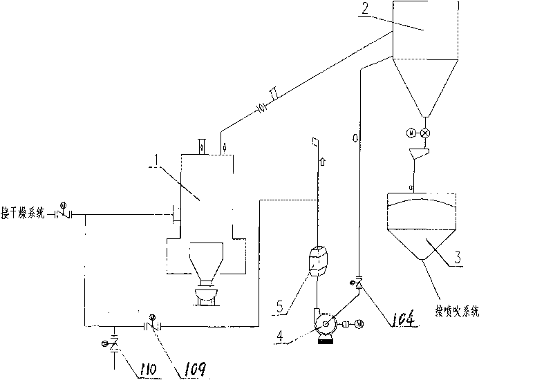
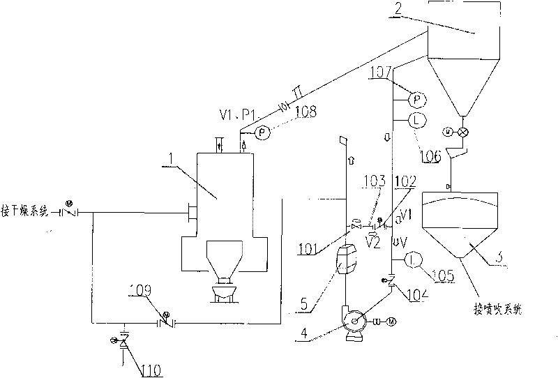
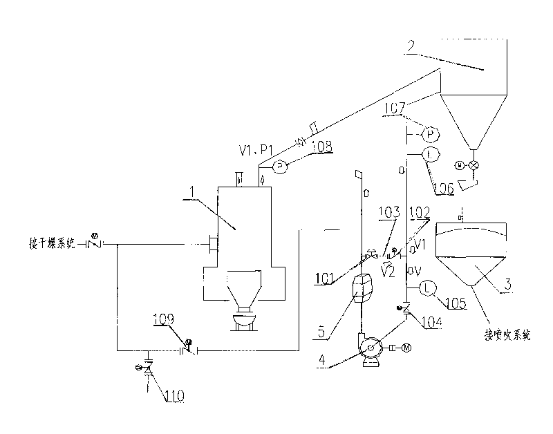
[0022] The hot air of the drying system is connected to the coal mill 1, and the pulverized coal is sent to the pulverized coal collection device 2 through the pneumatic conveying pipeline, and the pulverized coal is collected in the pulverized coal bin 3, and the exhaust gas is discharged through the pulverized coal fan 4 and the muffler 5 .

[0023] The other branch of the hot air of the drying system is equipped with electric butterfly valves 109 and 110, which are connected to the discharge pipeline behind the muffler 5.

[0024] Fan inlet valve 104 is installed at the inlet of pulverized coal fan 4 .

[0025] A communication pipe 103, a flow control valve 101 and an electric control valve 102 are installed between the waste gas pipeline from the pulverized coal collection device 2 to the pul...


PUM


Abstract

The invention discloses a method for setting and controlling a pulverized coal preparing system, belonging to the field of the controlling and adjusting technology. One branch of hot air of a drying system is connected to a coal pulverizer; the produced pulverized coal is fed into a pulverized coal collecting system through a pneumatic conveying pipe and is collected in a pulverized coal bunker; waste gas is discharged through a pulverized coal fan and a muffler; the other branch of hot air of the drying system is provided with an electric butterfly valve; the electric butterfly valve is connected with a waste gas exhaust pipe which is arranged at the rear of the muffler; and the a pulverized coal fan entrance valve is arranged on the entrance of the pulverized coal fan. The invention is characterized in that the waste gas exhaust pipe which is arranged at the rear of the muffler is communicated with a pulverized coal fan entrance pipe through a communicating pipe and an electric adjusting valve is arranged on the communicating pipe to adjust and control the air quality on the exist of the coal pulverizer and stabilize the negative pressure on the exist of the pulverizer so as to ensure than the pulverized coal fan operates under constant operating mode. The invention can improve the operating stability of the pulverized coal preparing system and can accurately select the type of the pulverized coal fan so as to appropriately reduce the capacity of the pulverized coal fan and save the energy and the resource.

Description

technical field [0001] The invention belongs to the technical field of control and adjustment, and discloses a system setting and control method of a pulverized coal preparation system. In the pulverized coal preparation system, the system setting and control method for adjusting the variable working conditions of the pulverized coal preparation and collection process. Background technique [0002] In the blast furnace smelting process, in order to reduce the amount of coke used, the pulverized coal injection process is widely used at present. Due to the impact of blast furnace ironmaking demand, overall coordination of the factory and furnace conditions, the iron production of the blast furnace is constantly changing, and the demand for pulverized coal is also constantly changing. In order to adapt to this change, it is necessary to adjust the pulverization quantity. [0003] The current design does not require pulverization and injection to achieve a dynamic balance, that...

Claims


Application Information

Patent Timeline
IPC IPC(8): B02C15/00B02C23/00B02C25/00
Inventor 张杰颜新吴波王贤
Owner CISDI ENG CO LTD
Learn More