Hydraulic pressure butterfly valve shaft sleeve installation machine and installation method

A butterfly valve shaft and installation machine technology, applied in metal processing, metal processing equipment, manufacturing tools, etc., can solve the problems of irregular manual operation, difficult to accurately locate, reduce production efficiency, etc., to improve working conditions and environment, eliminate Heavy physical labor, the effect of improving production efficiency

Active Publication Date: 2010-05-05
TIANJIN GALAXY VALVE
View PDF0 Cites 15 Cited by
  • Summary
  • Abstract
  • Description
  • Claims
  • Application Information

AI Technical Summary

Problems solved by technology

However, in the butterfly valve manufacturing industry, for a long time, the assembly of small and medium-sized butterfly valves is still mainly done by hand. In the assembly operation of pressing the shaft sleeves into the shaft holes of the upper and lower valve necks at both ends of the valve body, it is entirely by manpower and hammer. Knocking the shaft sleeve into the valve body has the disa

Method used


Image

  • Hydraulic pressure butterfly valve shaft sleeve installation machine and installation method
  • Hydraulic pressure butterfly valve shaft sleeve installation machine and installation method
  • Hydraulic pressure butterfly valve shaft sleeve installation machine and installation method

Examples


Embodiment Construction

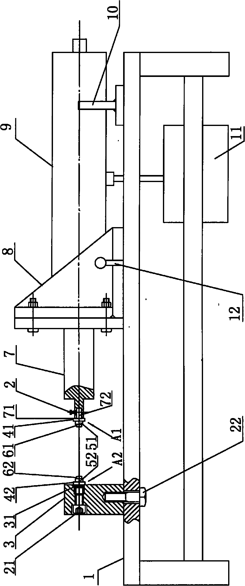
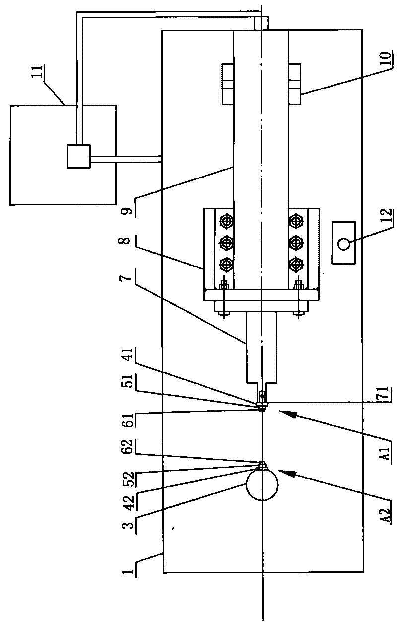
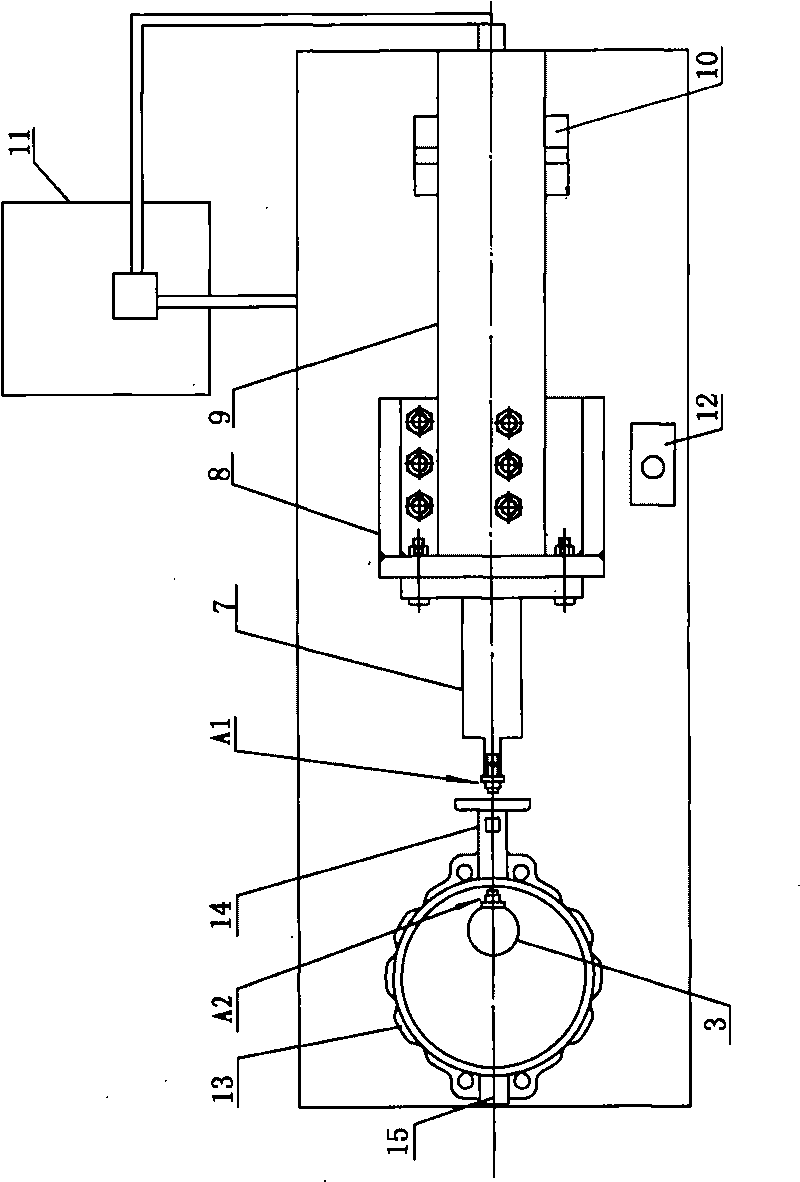
[0026] Figure 1-Figure 7 It shows a hydraulic butterfly valve shaft sleeve installation machine and its application diagram; the installation machine includes a workbench 1, which is characterized in that the above workbench is a rectangular stand, and is arranged and fixed at symmetrical intervals from right to left center along the longitudinal direction of the upper 1 workbench. The hydraulic cylinder 9 and the positioning block 3 on the work surface, the above-mentioned hydraulic cylinder is placed opposite to the positioning block 3 with its piston rod 7, and the end face 71 of the piston rod and the end face of the positioning block opposite to it are respectively arranged coaxially for the upper and lower valves. The neck sleeves 16, 19 are respectively pressed into the detachable right and left positioning pins A1, A2 in the upper and lower valve neck shaft holes 141, 151; Left flange 41,42, right and left shoulders 51,52 and right and left pin shaft ends 61,62, right...


PUM


Abstract

The invention relates to a hydraulic pressure butterfly valve shaft sleeve installation machine and an installation method thereof, and is characterized in that the installation machine is provided with a hydraulic cylinder and a located block which are fixed on a working platform surface from right to left; a right locating pin shaft and a left locating pin shaft which are used for respectively pressing an upper valve neck shaft sleeve and a lower valve neck shaft sleeve into an upper valve neck shaft hole and a lower valve neck shaft hole, are coaxial and are arranged on the end surface of the piston rod and relative located block end surface oppositely; a right flange, a left flange, a right shoulder, a left shoulder, a right pin shaft end and a left pin shaft end are coaxially arranged on a right locating pin shaft and a left locating pin shaft in a axisymmetric manner; the width of the right shoulder and the left shoulder which are in clearance fit with the upper valve neck shaft hole and the lower valve neck shaft hole is equal to the width of a circular ring spacer bush, also is equal to the sum of the width of the upper valve neck shaft sleeve and the thickness of a circle ring; the length of the right pin shaft end and the left pin shaft end is equal to the width of the upper valve neck shaft sleeve; and the external diameters of the spacer bush, the right flange and the left flange are more than the diameters of the upper valve neck shaft hole and the lower valve neck shaft hole. The method comprises the following steps: (1) two ends of the upper valve neck shaft hole are symmetrically pressed into a built-in shaft sleeve; (2) two end ports of the upper valve neck shaft hole are pressed with the shaft sleeve; and (3) the lower valve neck shaft hole is pressed into the shaft sleeve. The installation machine has the advantages of preventing heavy physical work of operators and ensuring product quality.

Description

technical field [0001] The invention relates to a butterfly valve assembly device and an assembly method, in particular to a hydraulic butterfly valve shaft sleeve installation machine and an installation method thereof. Background technique [0002] Butterfly valves are widely used in petroleum, gas, chemical, water treatment and other industrial fields because of their simple structure, small size, light weight, convenient and quick opening and closing, and good fluid control characteristics. They are also used in cooling water for thermal power plants system. The butterfly valve mainly includes a valve body, a valve seat, a valve plate and a valve shaft. The sleeves are separated by O-rings, and a sleeve is installed on the lower valve neck. In practical applications, butterfly valves are generally used in cylindrical passages, and their disc-shaped valve plates are installed along the radial direction of the pipeline, and rotate around the valve shaft between 0° and 90...

Claims


Application Information

Patent Timeline
IPC IPC(8): B23P19/027
Inventor 陈连印
Owner TIANJIN GALAXY VALVE
Why Eureka
Try Eureka