
Coating method of UV insulation moisture resisting agent

A moisture-proofing agent and coating technology, applied in the direction of tube/light screen manufacturing, etc., can solve the problems of large variation in the width of UV glue, long flow time, inability to cover the UV glue evenly, and achieve good coating uniformity. Effect

Inactive Publication Date: 2010-05-05
SICHUAN COC DISPLAY DEVICES
View PDF0 Cites 1 Cited by
  • Summary
  • Abstract
  • Description
  • Claims
  • Application Information

AI Technical Summary

Problems solved by technology

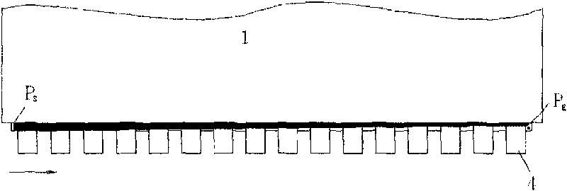
like figure 1 As shown, it is a commonly used coating method, and the entire coating side only has the beginning P S , end P E Two control points, coating in this way, due to the large coating distance, the difference in the width of the UV glue will vary greatly on the entire coating side, such as figure 2 As shown, P S The UV glue at the position of the control point is applied first, and the flow time is long, so the width is relatively large, while the end point P E The UV glue at the position is applied last, and the flow time is short, so the width is small; the result after curing is that the width of the beginning coating position is significantly larger than the width of the last coating position, and the position of the final coating TCP4 will not be evenly coated by the UV glue coverage
[0004] When setting the coating points, the general setting is to make the straight line formed by connecting the coating points parallel to the side of the PDP, so that figure 1 The control point P E For example, such as Figure 7 Shown is the control point P E The view of the longitudinal section, the control point P of the general UV insulation and moisture-proof agent 2 E It is very close to the edge of the PDP upper glass 11. Therefore, in actual production, the UV insulation and moisture-proof agent 2 will immediately flow to the edge of the PDP upper glass 11, but it takes a long time to flow to the edge of the PDP lower glass 12. time, such as Figure 8 As shown, the UV insulation and moisture-proof agent 2 is still difficult to flow to the edge of the PDP lower glass 12 after a long time

Method used


Image

  • Coating method of UV insulation moisture resisting agent
  • Coating method of UV insulation moisture resisting agent
  • Coating method of UV insulation moisture resisting agent

Examples


specific Embodiment 1

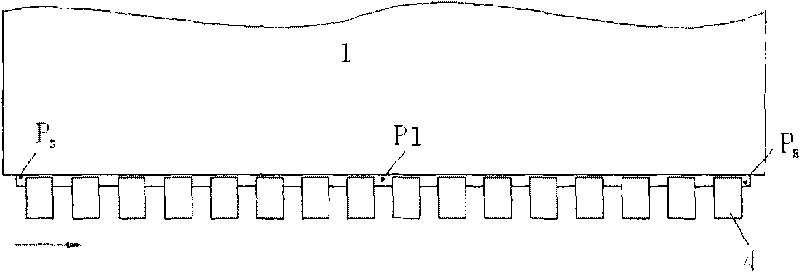
[0029] like image 3 As shown, the control point P starts on the coated side of the lower glass 12 of the PDP screen S and end control point P E Add a control point P between 1 , we call P1 For the first insertion control point, when the control point is set, the first insertion control point P 1 Relative to the starting control point P S Move S " towards the edge of the bottom glass 12 of the PDP screen 1 = 0.3mm, will end the control point P E relative to the first inserted control point P 1 Move S " towards the edge of the bottom glass 12 of the PDP screen 2 = 0.5mm, through the reasonable setting of the relative position relationship between the coating point and the edge of the lower glass 12 of the PDP screen, the UV insulating and moisture-proofing agent applied afterward can still flow quickly due to the short flow time. At the edge of the upper glass 11 of the PDP screen, at the same time, the problem that the UV insulating and moisture-proof agent flows slowly...

specific Embodiment 2

[0032] Such as Figure 5 As shown, the control point P starts on the coated side of the lower glass 12 of the PDP screen S and end control point P E increase P 1 and P 2 Two control points, we call P 1 is the first inserted control point, called P 2 For the second insertion control point, when the control point is set, the first insertion control point P 1 Relative to the starting control point P S Move S " towards the edge of the bottom glass 12 of the PDP screen 1 =0.2mm, insert the second control point P 2 relative to the first inserted control point P 1 Move S " towards the bottom glass 12 edge of PDP screen 2 =0.3mm, end control point P E point relative to the second inset control point P 2 Move S " towards the edge of the bottom glass 12 of the PDP screen 3 = 0.4mm, through the reasonable setting of the relative position relationship between the coating point and the edge of the lower glass 12 of the PDP screen, the UV insulating and moisture-proofing agent a...

specific Embodiment 3

[0035] Such as Figure 6 As shown, the control point P starts on the coated side of the lower glass 12 of the PDP screen S and end control point P E increase P 1 ,P 2 and P 3 Three control points, we call P 1 is the first inserted control point, called P 2 is the second insertion control point, called P 3 For the third insertion control point, when the control point is set, the first insertion control point P 1 Relative to the starting control point P S Move S " towards the edge of the bottom glass 12 of the PDP screen 1 =0.1mm, insert the second control point P 2 relative to the first inserted control point P 1 Move S " towards the bottom glass 12 edge of PDP screen 2 =0.2mm, insert the third control point P 3 point relative to the second inset control point P 2 Move S " towards the edge of the bottom glass 12 of the PDP screen 3 = 0.3mm, will end the control point P E point relative to the third inset control point P 3 Move S " towards the edge of the bottom ...


PUM


Abstract

The invention discloses a coating method of a UV insulation moisture resisting agent. N control point Ps are inserted between a start control point PS and a finish control point PE on a coating edge of a lower glass 12 of a PDP screen; the start control point PS and the finish control point PE are set; starting from the second control point, each control point is moved by S''n to the edge of the lower glass 12 of the PDP screen in sequence compared with the former control point; the length relation of two adjacent control points is set to be Sn+1=aSn, and the coating velocity relation between two adjacent control points is set to be Vn=bVn+1. The method of the invention can ensure that the whole coating uniformity of the coating edge is better.

Description

technical field [0001] The invention relates to the technical field of PDP modules, in particular to a method for applying a UV insulating and moisture-proof agent to a PDP module. Background technique [0002] After the PDP (Plasma Display Panel, plasma display panel) carries out the bonding process of TCP (Tape Carrier Package, circuit board with chip), FPC (Flexible Print Circuit, flexible circuit board) and PDP, in order to insulate and For moisture protection, it is necessary to apply UV insulation and moisture-proof agent. Since the PDP works at a relatively high voltage and temperature, some materials in the screen electrode are prone to short-circuit and other situations in the high-temperature, high-humidity, and high-voltage working environment, which will directly affect the life of the product. Therefore, UV The state of the insulating and moisture-proof agent coating is very important. The uneven coating width of UV insulation and moisture-proof agent will lea...

Claims


Application Information

Patent Timeline
IPC IPC(8): H01J9/20
Inventor 孙键昌
Owner SICHUAN COC DISPLAY DEVICES
Learn More