Tube-type spiral conveyer

A screw conveyor and tube-type technology, applied in the field of conveyors, can solve the problems of suspension bearings increasing the material blocking area, affecting normal work, and having no support devices, so as to reduce maintenance workload, maintenance costs, and weight. Effect

Inactive Publication Date: 2010-05-12
南通全通建筑机械有限公司
View PDF1 Cites 6 Cited by
  • Summary
  • Abstract
  • Description
  • Claims
  • Application Information

AI Technical Summary

Problems solved by technology

The hanging bearing increases the material blocking area, which affects the improvement of the conveying capacity, and because it works in a dusty environment, the sealing and lubrication of the hanging bearing has always been a difficult problem to solve, and the replacement is labor-intensive and time-consuming, which affects the normal work; The groove is U-shaped, covere

Method used


Image

  • Tube-type spiral conveyer
  • Tube-type spiral conveyer
  • Tube-type spiral conveyer

Examples


Embodiment Construction

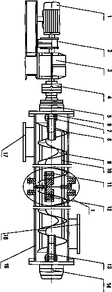
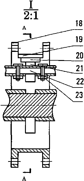
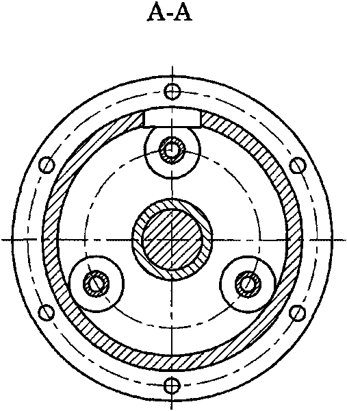
[0014] Such as figure 1 Shown is a schematic structural view of the tubular screw conveyor of the present invention, in which the motor 1 is connected to the reducer 3 through a coupling 2, the reducer 3 is connected to one end of the head shaft 6 through a coupling 4, and the head shaft 6 passes through the head The other end of the bearing device 5 is inserted into the short pipe 8 on the spiral body 11, and is fastened by the pin shaft 7; the two ends of the spiral body 11 are welded by a short pipe 8 slightly larger than one pitch, several spiral blades 9, and three seamless steel pipes 10 Formed, the helical blades 9 are connected continuously at the same angle, and three seamless steel pipes 10 penetrate into the holes uniformly distributed along the circumference of the helical surface at an appropriate radius, and are parallel to the axis, and are equal in length to the helical body 11 for connection and support. The function of the spiral body 11; the short tube 8 of ...


PUM


Abstract

The invention discloses a tube-type spiral conveyer which comprises a motor, a coupling, a speed reducer, a head bearing device, a tail bearing device, a delivery pipe, a support tube, a spirochaeta, and a material inlet and a material outlet on the delivery pipe, wherein the spirochaeta is formed by the welding of a stub pipe, a spiral blade and three seamless steel tubes; the three seamless steel tubes are all distributed at a proper radius part of the circumference of a helicoid, and are parallel to an axes, and have the same length with the spirochaeta; the middle circumference of the support tube is uniformly distributed with three rollers which are coaxial with the seamless steel tubes, inner holes of the three rollers are in clearance fit with a connecting shaft, and outer circles thereof are connected with inner wall of the support tube in a rolling manner. In the invention, as a suspension bearing is eliminated, and the three rollers that are uniformly distributed on the circumference of the spirochaeta are adopted to be contacted with the inner wall of the tube in the rolling manner, and the rollers are not easy to be damaged and do not need lubrication, therefore maintenance load is alleviated, maintenance cost is reduced, and use time is prolonged; and the delivery pipe and the support tube are connected by a flange, thus having good tightness and being especially suitable for delivering powdery materials.

Description

technical field [0001] The invention relates to a conveyor for horizontally conveying powdery materials, in particular to a tubular screw conveyor. Background technique [0002] Existing horizontal screw conveyor is that the spiral blades are continuously welded on the pipe shaft to form a certain length of spiral body, and the spiral body and the spiral body are connected by "shaft type" or "flange type". When the distance of the screw conveying material exceeds 3 meters, in order to prevent the screw shaft from bending, a hanging bearing is installed at the connection. The hanging bearing increases the material blocking area, which affects the improvement of the conveying capacity, and because it works in a dusty environment, the sealing and lubrication of the hanging bearing has always been a difficult problem to solve, and the replacement is labor-intensive and time-consuming, which affects the normal work; The groove is U-shaped, covered with a cover plate, and dust of...

Claims


Application Information

Patent Timeline
IPC IPC(8): B65G33/14B65G33/24B65G33/26
Inventor 李正峰
Owner 南通全通建筑机械有限公司
Why Eureka
Try Eureka