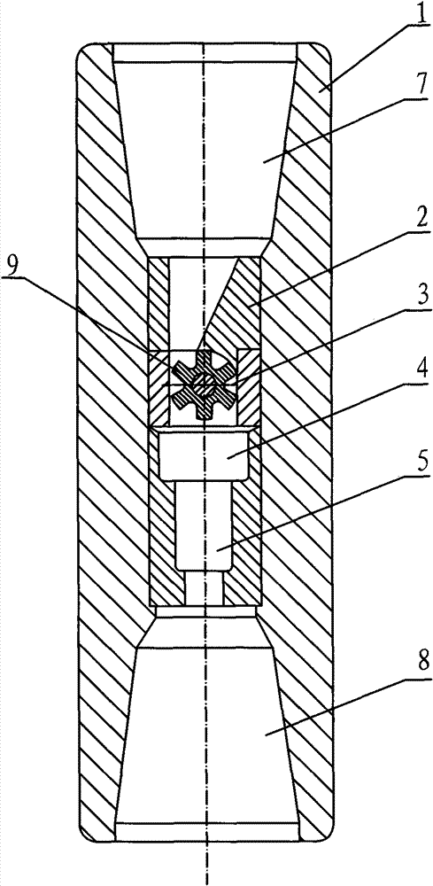
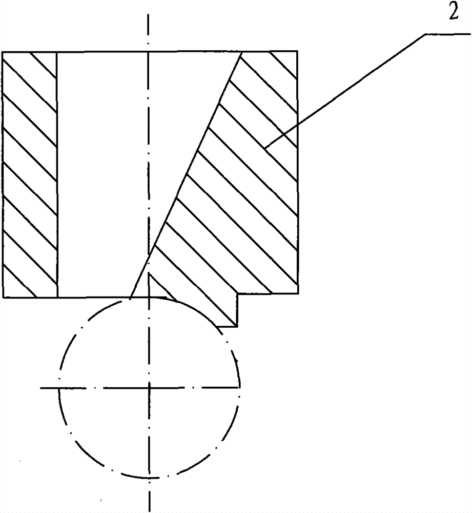
Hydraulic pulse cavitation jet well drilling method
A hydraulic pulse and jet technology, used in drilling with liquid/gas jets, etc., can solve the problems of increased confining pressure, decreased jet impact effect, and weakened cavitation capability, and can extend service life, ensure downhole safety, and improve mechanical properties. The effect of drilling speed
- Summary
- Abstract
- Description
- Claims
- Application Information
AI Technical Summary
Problems solved by technology
Method used
Image
Examples
Embodiment 1
[0039] figure 1 This is a flowchart of Embodiment 1 of the method of the present invention. The specific steps of the hydraulic pulse cavitation jet drilling method are as follows:
[0040] Step 101: During the drilling operation, the continuous and stable liquid flow used for impacting the bottom of the well is converted into a pulsed resonance flow liquid;
[0041] Step 102: Inject the pulsed resonance flowing liquid into a relatively static liquid at a high speed to cause cavitation;
[0042] Step 103: Impulse the pulse resonance flowing liquid that produces cavitation into the bottom of the well in a fluctuating pressure manner.
[0043] In the above preferred embodiment, the pulsating flow of the liquid can be generated by periodic disturbance of the continuous and stable liquid flow according to a preset frequency.
[0044] In the above embodiment, the continuous fluid forms acoustic resonance through the resonant cavity, so that the jet at the nozzle outlet becomes an intermitt...
Embodiment 2
[0047] This embodiment is a more detailed solution process than that of Embodiment 1. details as follows:
[0048] Step 1010: During the drilling operation, convert the continuous and stable liquid flow used for impacting the bottom of the well into a pulsed resonance flowing liquid; periodically perturb the continuous and stable liquid flow according to a preset frequency;
[0049] Step 1021: The resonant cavity of the organ tube can form an acoustic resonance, so that the jet at the nozzle outlet becomes an intermittent vortex circulation, which induces cavitation;
[0050] Step 1022: The rotating impeller can disturb the continuous fluid and enhance the discontinuity of the fluid, thereby enhancing cavitation;
[0051] Step 1031: Make the pressure of the pulse resonance flowing liquid fluctuate;
[0052] Step 1032: Make the pulse resonance flowing liquid with pressure fluctuations generate feedback pressure resonance;
[0053] Step 1033: Use the pressure resonance to generate fluid ...
Embodiment 3
[0058] This example is based on Figure 13 When assembling and using, the specific steps are as follows:
[0059] Step 201: Introduce a continuous and stable liquid flow for impacting the bottom of the hole during the drilling operation of the drilling tool;
[0060] Step 202: Periodically disturb the continuous and stable liquid flow to form a pulsed flow liquid to increase the impact effect;
[0061] Step 203: Amplify the pulse flowing liquid and make it resonate, and then convert it into a pulse resonance flowing liquid;
[0062] Step 204: By reducing the cross-sectional area of the fluid and speeding up its flow rate, it is injected into the relatively static environmental liquid at a high speed;
[0063] Step 205: Make the liquid form a turbulence to generate cavitation;
[0064] Step 206: Flow the high-speed pulse resonant flowing liquid that generates the cavitation phenomenon into the organ tube nozzle on the drill bit in a fluctuating pressure manner;
[0065] Step 207: The ca...
PUM
 Abstract
Description
Claims
Application Information
 - R&D
- Intellectual Property
- Life Sciences
- Materials
- Tech Scout
- Unparalleled Data Quality
- Higher Quality Content
- 60% Fewer Hallucinations
Browse by: Latest US Patents, China's latest patents, Technical Efficacy Thesaurus, Application Domain, Technology Topic, Popular Technical Reports.
© 2025 PatSnap. All rights reserved.Legal|Privacy policy|Modern Slavery Act Transparency Statement|Sitemap|About US| Contact US: help@patsnap.com


