Coriolis mass flow transmitter based on DSP

A mass flow and transmitter technology, applied in direct mass flowmeters, mass flow measurement devices, volume change compensation/correction devices, etc., can solve the problems of long convergence process, difficult real-time realization, small differential amplifier amplitude, etc. , to achieve the effect of improving calculation accuracy and shortening convergence time

Active Publication Date: 2010-05-12
GOLDCARD HIGH TECH
View PDF5 Cites 33 Cited by
  • Summary
  • Abstract
  • Description
  • Claims
  • Application Information

AI Technical Summary

Problems solved by technology

The problem with this method is: the phase difference of the two sensor signals is very small (generally less than 4 degrees), so the amplitude of the differential amplifier is very small, and it is very susceptible to noise interference; the compensation method takes too much time, because the calculation of the phase difference once Need to collect 6 signals
[0008] A DSP-based digital signal processing system was designed in the US patent US-5555190 granted to H.V.Derby et al. on September 10, 1996 and the Chinese patent CN-1190461A granted on August 12, 1998. Adaptive Linear Enhancement (ALE) technique and apparatus to accurately determine the frequency and phase relationship between vibrating flow tubes to more accurately determine mass flow through a mass flow meter. Derby's patent has two embodiments, each of The signal processing link is composed of three parts: multi-decimation-filtering, frequency estimation/linear enhancement and phase difference calculation. The multi-decimation part of the two embodiments adopts (8:1 and 6:1 two-stage extraction), and the phase difference calculation adopts improved The Goertzel algorithm. The two embodiments are only different in the frequency estimation/linear enhancement part. The ALE of the fi

Method used


Image

  • Coriolis mass flow transmitter based on DSP
  • Coriolis mass flow transmitter based on DSP
  • Coriolis mass flow transmitter based on DSP

Examples


Embodiment Construction

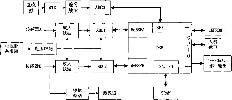
[0035] The system hardware block diagram of the present invention is as figure 1 Shown. The system of the present invention consists of Coriolis mass flow sensor (including magnetoelectric speed sensor A, magnetoelectric speed sensor B, vibration exciter, resistance temperature sensor RTD), amplifying filter circuit, analog-to-digital converter ADC1, and analog-to-digital conversion ADC2, voltage reference source, voltage follower, current source, differential amplifier, analog-to-digital converter ADC3, analog drive module, digital signal processor DSP minimum system, external expansion SARAM, external expansion EEPROM, man-machine interface, 4-20mA Current output, pulse output, and power supply module. The system of the present invention is divided into multiple circuit boards according to functions. The most important ones are analog board and digital board. The former includes sensor signal conditioning and acquisition circuit, analog drive circuit and temperature compensat...


PUM


Abstract

The invention relates to the field of flow detection, and provides a Coriolis mass flow transmitter based on DSP, which comprises an amplifying filter circuit, an analog-to-digital converter 1, an analog-to-digital converter 2, a voltage reference source, a voltage follower, a current source, a difference amplifier, an analog-to-digital converter 3, a simulation driver module, a digital signal processor DSP minimum system, an expanding SRAM, an expanding EEPROM, a man-machine interface, 4-20mA current output and pulse output, a power module and a software. The simulation driver module stimulates a vibration exciter in the Coriolis mass flow transmitter so as to lead a flow tube to vibrate with natural frequency. Two magnetoelectric sensors positioned at two sides of the flow tube output two ways of sine-wave signals which are amplified and filtered by two ways of conditioning circuits with same parameter, then respectively and simultaneously sampled by two analog-to-digital converters with same model, and converted in digital value, and delivered to DSP by two multichannel buffered serial ports of the DSP. DSP adopts digital filter to eliminate the noise of the signals, is self-adaptive to a lattice notch filter to calculate the frequency, and then adopts the DTFT algorithm taking negative frequency into account to calculate to phase difference, thus obtaining the mass flow finally.

Description

Technical field [0001] The invention relates to the field of flow detection, and is a DSP-based Coriolis mass flow transmitter, in particular to a digital filter to filter the signal, an adaptive lattice notch filter to calculate the signal frequency, and then to take into account the negative The frequency DTFT algorithm calculates the phase difference of the Coriolis mass flowmeter signal processing system and analog drive system. Background technique [0002] Coriolis mass flowmeter (hereinafter referred to as Coriolis mass flowmeter) can directly measure mass flow. It is one of the most rapidly developing flowmeters and has broad application prospects. Coriolis mass flowmeter consists of two parts, one is the sensor part, including the magnetoelectric speed sensor, vibration exciter and temperature sensor, and the other is the transmitter, which includes signal conditioning, processing and driving. As for the signal conditioning and processing part, it is required to accurat...

Claims


Application Information

Patent Timeline
IPC IPC(8): G01F1/84G01F15/02
Inventor 徐科军朱永强李叶侯其立李苗
Owner GOLDCARD HIGH TECH
Why Eureka
Try Eureka