
ASE light source

A light source and optical isolator technology, which is applied in the direction of lasers, laser components, and the structure/shape of active media, can solve problems such as leakage, damage to light wave total reflection conditions, and affect the lateral distribution of optical fiber mode fields, so as to reduce bending loss , the effect of strong binding ability

Inactive Publication Date: 2010-05-12
刘承香 +3
View PDF0 Cites 3 Cited by
  • Summary
  • Abstract
  • Description
  • Claims
  • Application Information

AI Technical Summary

Problems solved by technology

[0002] In practical applications, when the optical fiber is used as a transmission medium, it will inevitably need to be bent. The bending loss of the traditional optical fiber is mainly due to the deformation caused by bending, which changes the symmetrical geometric structure of the optical fiber and the relative refraction between the core and the cladding. rate, which affects the lateral distribution of the fiber mode field, and destroys the total reflection condition of light wave transmission along the fiber, resulting in the leakage of light energy to the cladding or even the outer medium

Method used


Image

  • ASE light source
  • ASE light source
  • ASE light source

Examples


Embodiment Construction

[0016] In order to make the object, technical solution and advantages of the present invention clearer, the present invention will be further described in detail below in conjunction with the accompanying drawings and embodiments. It should be understood that the specific embodiments described here are only used to explain the present invention, not to limit the present invention.

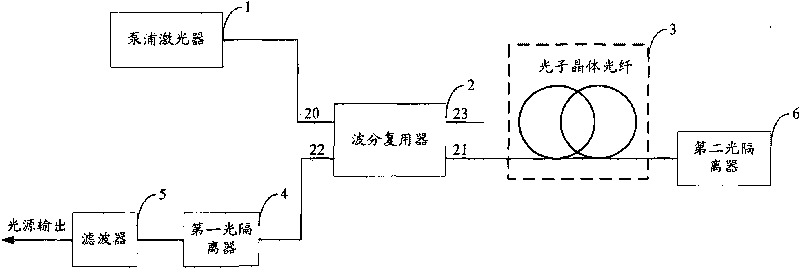
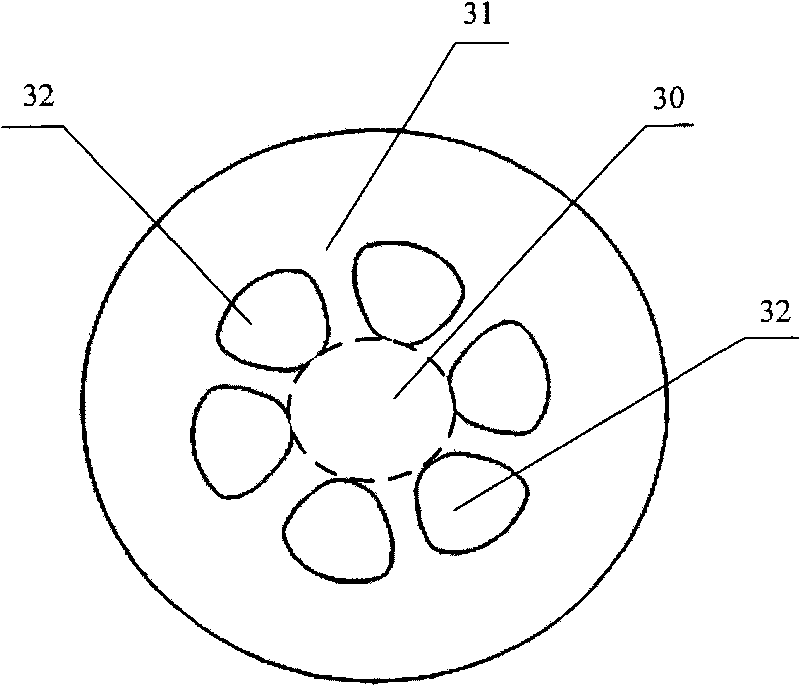
[0017] The ASE light source provided by the embodiment of the present invention uses a photonic crystal fiber with pomelo-shaped air holes, which reduces the bending loss of the fiber light source, enhances the ability to resist deformation, and reduces the size of the light source.

[0018] The photonic crystal fiber broadband light source provided by the embodiment of the present invention can be applied to the fields of fiber optic sensing and fiber optic communication. figure 1 The structure of the ASE light source with a one-way backward structure provided by the embodiment of the present inve...


PUM


Abstract

The invention is applicable to the fields of optical fiber sensing, an optical fiber gyro, optical fiber communication and the like, and provides an ASE light source which comprises a wavelength division multiplexer, a pump laser connected with an input end of the wavelength division multiplexer, a first opto-isolator connected with a second output end of the wavelength division multiplexer, and a photonic crystal optical fiber connected with a first output end of the wavelength division multiplexer, wherein the photonic crystal optical fiber further comprises a fiber core and a cladding layer used for covering the fiber core; and the cladding layer is provided with a shaddock-shaped air vent hole. By adopting the photonic crystal optical fiber provided with the shaddock-shaped air vent hole, the ASE light source reduces the effective refractive index of the cladding layer so as to lead greater refractive index difference to be formed between the fiber core and the cladding layer, has stronger constraint capability for electromagnetic field, reduces the bending loss and decreases the size of an optical fiber light source.

Description

technical field [0001] The invention belongs to the fields of fiber optic gyroscope, fiber optic sensor, fiber optic communication and the like, and in particular relates to an amplified spontaneous emission (Amplified spontaneous emission, ASE) light source. Background technique [0002] In practical applications, when the optical fiber is used as a transmission medium, it will inevitably need to be bent. The bending loss of the traditional optical fiber is mainly due to the deformation caused by bending, which changes the symmetrical geometric structure of the optical fiber and the relative refraction between the core and the cladding. rate, which affects the lateral distribution of the fiber mode field, and destroys the total reflection condition of light wave transmission along the fiber, resulting in the leakage of light energy to the cladding or even the outer medium. Contents of the invention [0003] The purpose of the embodiments of the present invention is to pro...

Claims


Application Information

Patent Timeline
Patent Type & Authority Applications(China)
IPC IPC(8): H01S3/067H01S3/094H01S3/06
Inventor 刘承香阮双琛张力
Owner 刘承香
Learn More