Permanent magnet track brake

A technology of magnetic rail brake and permanent magnet, which is applied in the direction of brakes interacting between braking elements and rails, asynchronous inductive clutches/brakes, railway braking systems, etc. , permanent magnet demagnetization and other problems, to improve the braking effect, avoid wear and tear, and reduce the braking distance

Inactive Publication Date: 2010-05-19
JIANGSU UNIV
View PDF0 Cites 8 Cited by
  • Summary
  • Abstract
  • Description
  • Claims
  • Application Information

AI Technical Summary

Problems solved by technology

The disadvantages of this structure and working method are: the braking force is not easy to control, the permanent magnet and the track wear s

Method used


Image

  • Permanent magnet track brake
  • Permanent magnet track brake
  • Permanent magnet track brake

Examples


Embodiment Construction

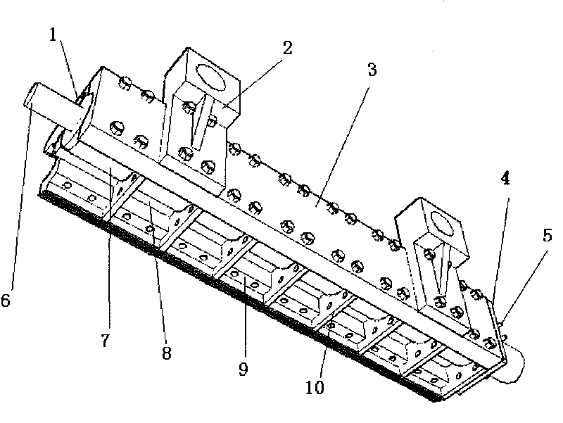
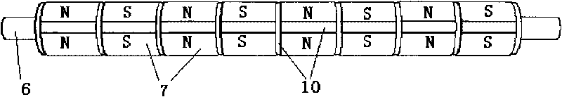
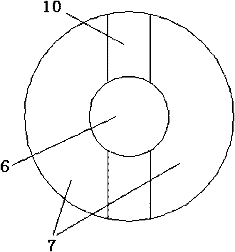
[0016] Such as Figure 1-3 As shown, the permanent magnet rail brake has a permanent magnet shaft 6. An even number of permanent magnets 7 are arranged on the outer ring of the permanent magnet shaft 6. The cross-sectional shape of the permanent magnet 7 is formed by an arc and chord length smaller than a semicircle. The N and S poles of the magnet 7 are arranged alternately and with opposite polarities along the axial direction of the permanent magnet shaft 6, and the permanent magnets 7 with the same polarity are arranged symmetrically at intervals along the central axis of the permanent magnet shaft 6. A partition 10 is provided at the gap positions of the N pole and the S pole of the permanent magnet 7 in the horizontal and vertical directions. The partition 10 is made of a non-magnetic material and is in close contact with the permanent magnet 7. The cross section of the partition 10 and the cross section of the permanent magnet 7 are combined in a circular shape.

[0017] ...


PUM


Abstract

The invention discloses a permanent magnet track brake. An outer ring of a permanent magnet axis is provided with permanent magnets of which the number is even; N and S poles of the permanent magnets are arranged alternately at intervals in turn along the axial direction of the permanent magnet axis in a way that the polarities are opposite; the permanent magnets with the same polarity are arranged symmetrically about the central axis of the permanent magnet axis at intervals; clapboards are arranged at transverse and longitudinal gaps of the N and S poles of the permanent magnets; pole shoes are arranged symmetrically on two sides and fixedly arranged close to the permanent magnets; the pole shoes correspond to S and N poles of the permanent magnets in the axial direction of the permanent magnet axis, the length of the pole shoes is consistent with that of the N and S poles, and the number of the pole shoes is the same as that of the permanent magnets; the clapboards are extended to gaps of adjacent pole shoes; eddy current braking and friction braking are realized according to different running speeds of railway vehicles, the abrasion of the pole shoes and rails is avoided, and the braking is realized and the service life of the pole shoes is prolonged simultaneously; the braking effect is improved; and the braking force is changed by controlling the rotating angle of the permanent magnet axis so as to realize safe and stable braking of the railway vehicles.

Description

Technical field [0001] The invention relates to a magnetic track brake of a railway train vehicle, which realizes the brake or release of the railway train vehicle. Background technique [0002] The use of joint control of multiple braking methods in rail vehicles will greatly guarantee the driving safety of high-speed rail vehicles. At present, the use of disc brakes is widely promoted in railway passenger vehicles, which reduces the thermal damage of the wheel treads compared with tread brakes. However, as a kind of adhesion brake, the braking force produced by disc brake is still limited by adhesion conditions. Although the anti-skid device can be used to bring the braking force close to the adhesion limit, when it is necessary to further increase the speed of the train, the braking distance in the technical specifications must be modified to meet the needs of the vehicle speed. Therefore, the development of quasi-high-speed and high-speed railways When it comes to new urban...

Claims


Application Information

Patent Timeline
IPC IPC(8): B61H7/00H02K49/04
Inventor 姚明何仁
Owner JIANGSU UNIV
Why Eureka
Try Eureka