Multifunctional sleeve type energy dissipation valve

A sleeve-type, multi-functional technology, applied in the direction of functional valve types, valve details, safety valves, etc., can solve the problems of inability to fully utilize energy dissipation and eliminate cavitation, valve flaps cannot achieve pressure balance, pipe network vibration and noise, etc. No problem, achieve the effect of no life limit, reliable structure, and small running resistance

Active Publication Date: 2011-04-20
HUNAN PUMP VALVE MFG CO LTD
View PDF0 Cites 0 Cited by
  • Summary
  • Abstract
  • Description
  • Claims
  • Application Information

AI Technical Summary

Problems solved by technology

However, in practical applications, when the pressure difference between the inlet and outlet is large, especially when the outlet pressure P2 discussed is close to 0, since the upper chamber, lower chamber and valve disc of the diaphragm are all subjected to the inlet pressure P1 at this time, there is also a valve The pressure of the spring above the disc makes the valve disc unable to achieve pressure balance at a low opening, so the opening and closing of the valve disc fluctuates, resulting in strong vibration and noise in the pipe network during operation
Unable to give full play to its advantages of energy dissipation and cavitation elimination

Method used


Image

  • Multifunctional sleeve type energy dissipation valve
  • Multifunctional sleeve type energy dissipation valve
  • Multifunctional sleeve type energy dissipation valve

Examples


Embodiment Construction

[0012] The present invention will be further described below in conjunction with the accompanying drawings and specific embodiments.

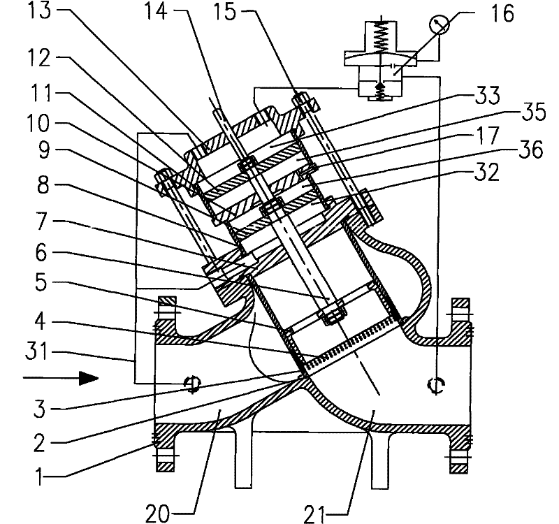
[0013] For the structure of decompression multifunctional sleeve type energy dissipation valve, see figure 1 There is a valve seat 2 between the water inlet 20 and the water outlet 21 of the valve body 1, and a sleeve 3 is installed on the valve seat 2 through the flange hole in the valve body, and the sleeve 3 is installed on the flange of the valve body through the The valve cover 7 is positioned, and the sleeve 3 separates the water inlet 20 and the water outlet 21 of the valve body. The sleeve 3 is provided with radial holes 4 along the axial wall, which are opposite to each other. The sleeve 3 is provided with an adjusting cylinder 5. The regulating cylinder 5 is a cylindrical member connected up and down. The valve cover 7 is provided with a small piston cylinder 8 and a small piston 9 and a large piston cylinder 11 and a large piston 12....


PUM


Abstract

The invention discloses a multifunctional sleeve type energy dissipation valve. A lower end of a valve shaft is connected with an adjusting cylinder. An upper end of the valve shaft is connected with big and small piston units which are disposed on a valve cover by passing through the valve cover. The lower cavity of the big piston and the upper cavity of the small piston are communicated with atmosphere. A water inlet of the valve is respectively connected with the lower cavity of the small piston and the upper cavity of the big piston by a first by-pass accessory. A water outlet of the valve is communicated with the upper cavity of the big piston by a decompressing end of a decompressing valve. Or, the water inlet of the valve is respectively connected with the lower cavity of the smallpiston, the upper cavity of the big piston and a control end of a decompression guiding valve by a second by-pass accessory, and the water outlet of the valve is communicated with the upper cavity ofthe big piston (33) by a decompressing end of the decompression guiding valve. The invention is a multifunctional self-force sleeve type energy dissipation valve which has reliable structure, stable property, functions of dissipating energy and gas etching and can adapt to high-differential working conditions and can be applied to pressure reduction and decompression working conditions.

Description

technical field [0001] The invention relates to a valve for controlling the outlet of a water pump, in particular to a valve with a sleeve structure driven and controlled by hydraulic force in a pipeline. technical background [0002] Chinese patent 0222909.7 discloses a porous sleeve type hydraulic control pressure reducing valve, which is characterized in that through the perforated sleeve set in the valve body, the fluids collide with each other when passing through the valve to achieve energy dissipation and reduce cavitation. However, in practical applications, when the pressure difference between the inlet and outlet is very large, especially when the outlet pressure P2 discussed is close to 0, since the upper cavity, lower cavity and valve disc of the diaphragm are all subjected to the inlet pressure P1 at this time, and there is also a valve The pressure of the spring above the disc makes the valve disc unable to achieve pressure balance at a low opening, so the open...

Claims


Application Information

Patent Timeline
Patent Type & Authority Patents(China)
IPC IPC(8): F16K17/02F16K37/00F16K47/00F16K31/12
Inventor 朱铁强左正良滕达李志鹏
Owner HUNAN PUMP VALVE MFG CO LTD
Why Eureka
Try Eureka