Flat plane antenna applicable to mobile satellite communication terminal

A mobile satellite communication and planar antenna technology, which is applied in the antenna field of mobile satellite communication terminals, can solve the problems of complex feeding network, limited application range, and unacceptable loss, and achieve the effect of low profile, reduced profile, and reduced volume

Active Publication Date: 2010-05-19
CHINA ELECTRONIC TECH GRP CORP NO 38 RES INST
View PDF0 Cites 17 Cited by
  • Summary
  • Abstract
  • Description
  • Claims
  • Application Information

AI Technical Summary

Problems solved by technology

Conventional waveguide slot dual-polarization antennas are realized by using two different slots, requiring two sets of feed networks, which require a large space for arrangement, resulting in a very comp

Method used


Image

  • Flat plane antenna applicable to mobile satellite communication terminal
  • Flat plane antenna applicable to mobile satellite communication terminal
  • Flat plane antenna applicable to mobile satellite communication terminal

Examples


Embodiment 1

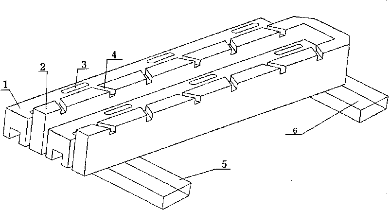
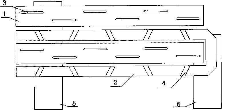
[0039] see figure 1 , figure 2 with image 3 , a planar antenna suitable for mobile satellite communication terminals, including two vertically polarized arrays, two horizontally polarized arrays and two feeding waveguides. The array is formed into a rectangular radiation waveguide 2 with narrow side radiation slant slots.

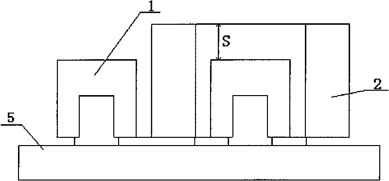
[0040] The vertically polarized array is a ridge waveguide 1 wide-side radiating longitudinal slot 3 resonant array, and the horizontally polarized array is a rectangular radiating waveguide 2 narrow-side radiating oblique slot 4 resonant array. Two ridge waveguides 1 and two radiating waveguides 2 are placed parallel and side by side to form a dual polarization linear array, see figure 2 ; Two independent ridge waveguides 1 and radiating waveguides 2 are placed with one broad side facing up and the other narrow side facing up. The ends of two adjacent radiation waveguides 2 are connected by a U-shaped waveguide bend. The heights of the two waveguid...

Embodiment 2

[0051] see figure 1 , Figure 11 , a planar antenna suitable for mobile satellite communication terminals, including a vertically polarized array, a horizontally polarized array and two feeder waveguides, the vertically polarized array is a ridge waveguide 1 with a broad-side radiating longitudinal slot, and the horizontally polarized array is a waveguide with Rectangular radiating waveguide 2 with narrow radiating oblique slots. The antenna has a ridge waveguide 1 and a rectangular radiation waveguide 2 alternately placed, and forms a dual-polarized line source through two types of slots, see figure 1 . The dual-polarized antenna array is composed of these alternately placed dual-polarized line sources, see Figure 11 , is a 6×8 unit antenna array.

[0052] The aperture dimension of the ridge waveguide 1 in the above-mentioned dual-polarized antenna front is k=9.5mm, the height is 7mm, and the ridge height is 3mm. The narrow side slanted waveguide is a rectangular radiat...


PUM

PropertyMeasurementUnit
Caliber sizeaaaaaaaaaa

Abstract

The invention relates to an antenna applicable to mobile satellite communication terminal. The antenna comprises two vertically-polarized arrays, two horizontally-polarized arrays and two feeding waveguides, the vertically-polarized arrays are ridge waveguides with broad side radiate longitudinal seam, the horizontally-polarized arrays are rectangular radiate waveguides with narrow side radiate inclined seam. The invention is characterized in that the two ridge waveguides and the two radiate waveguides are arranged parallel in a stagger way to form a double-polarized array; the height of the radiate waveguides is higher than that of the ridge waveguides; one v is arranged on the bottom of one end of the double-polarized array in an orthogonal way; the inclined coupling seam and the coupling longitudinal seam which are communicated are respectively arranged between the two ridge waveguides and the feeding waveguides and between the two radiate waveguides and the feeding waveguides. Theinvention integrates the antenna with the feeder by coupling and feeding, thus greatly reducing height and weight of the antenna, and simplifying the structure of the antenna and the design of the feeding network. The invention has low profile but high gain, and is very suitable for satellite communication terminal of mobile carrier.

Description

technical field [0001] The invention belongs to the technical field of communication, and particularly relates to an antenna suitable for a mobile satellite communication terminal. technical background [0002] Satellite communication can not only realize confidential communication, but also has a large communication coverage area, long communication distance, and communication cost does not increase with the increase of distance. Satellite communication can not only carry out voice communication but also transmit data, fax and images. Therefore, satellite communication has been widely used in various industries, especially in some places where ordinary communication cannot be realized, such as the vast ocean. Satellite communication makes up for the shortcomings of GSM (GPRS), CDMA and other mobile communication systems that need to rely on a large number of base stations, so that people can communicate well at any time, any place, and under any circumstances (even during ...

Claims


Application Information

Patent Timeline
IPC IPC(8): H01Q13/10H01Q13/08H01Q1/22
Inventor 吴瑞荣汪伟邹永庆齐美清张洪涛杨揆汤艳燕
Owner CHINA ELECTRONIC TECH GRP CORP NO 38 RES INST
Why Eureka
Try Eureka