Current sharing control circuit and control method of double-current sharing buses of parallel DC switch power supply

A DC switch and current sharing bus technology, applied in the field of control, can solve the problems of power supply and load reliability, adverse effects on safety, overvoltage, power supply voltage reduction, etc., and achieve the effect of good redundancy and anti-interference.

Inactive Publication Date: 2010-05-19
HARBIN ENG UNIV
View PDF0 Cites 16 Cited by
  • Summary
  • Abstract
  • Description
  • Claims
  • Application Information

AI Technical Summary

Problems solved by technology

[0004] (1) In the master-slave current sharing method, there must be a communication link between the master and slave power supplies, resulting in a complex system structure; if the master power supply fails, the entire power supply system cannot work normally, so this method is not suitable for redundant parallel systems
[0005] (2) Adding a current sharing controller The current sharing method requires an additional current sharing controller, and its disadvantages are similar to those of the master-slave current sharing method
[0006] (3) Although the average current sharing method can accurately realize current sharing, when the bus is short-circuited or a power supply connected to the bus fails to work, the voltage of the bus will drop, and the voltage of each power supply will be lowered, even reaching its lower limit. cause malfunction
[0007] (4) Although the maximum current sharing method is widely used due to its good redundancy (it will not affect the operation of the ent

Method used


Image

  • Current sharing control circuit and control method of double-current sharing buses of parallel DC switch power supply
  • Current sharing control circuit and control method of double-current sharing buses of parallel DC switch power supply
  • Current sharing control circuit and control method of double-current sharing buses of parallel DC switch power supply

Examples


Embodiment Construction

[0029] The present invention is described in more detail below in conjunction with accompanying drawing example:

[0030] The first implementation mode of the parallel DC switching power supply dual current sharing busbar current sharing control circuit of the present invention is as follows:

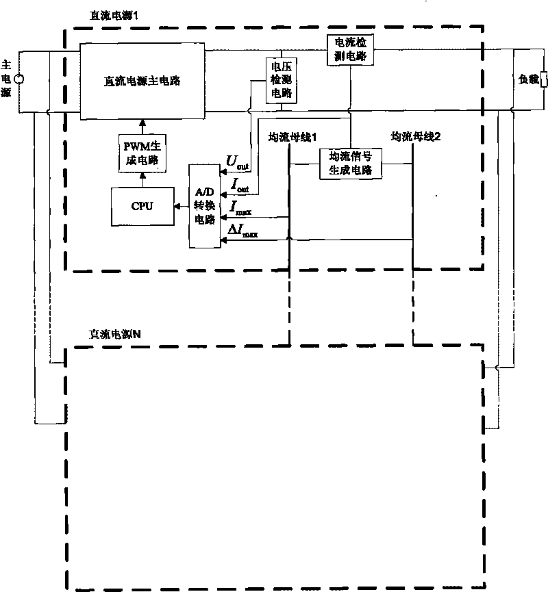
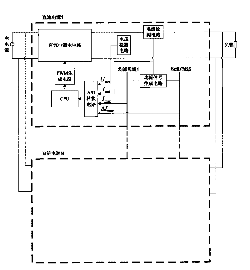
[0031] combine figure 1 shown. There are N (N=1, 2, . . . ) DC switching power supplies running in parallel, which are DC power supply 1 to DC power supply N respectively. All these supplies are connected through two different common current-sharing buses.

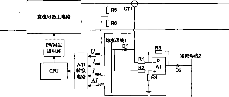
[0032] In addition to the hardware circuit structure including the DC power supply main circuit, the central processing unit CPU, the PWM generation circuit, the A / D conversion circuit, the voltage detection circuit, and the current detection circuit, it also has its unique current sharing signal generation circuit and current sharing circuit. Busbar 1, current sharing busbar 2, etc.

[0033] The main circuit of the DC power sup...


PUM


Abstract

The invention provides current sharing control circuit and control method of double-current sharing buses of a parallel DC switch power supply. The current sharing control circuit comprises N DC switch power supplies which operate in parallel connection, wherein N = 1, 2, and the like; all the DC switch power supplies are connected together through two different common current sharing buses, and each DC switch power supply comprises a DC power supply main circuit, a central processing unit (CPU), a PWM generation circuit, an A/D conversion circuit, a voltage detection circuit, a current detection circuit, a current sharing signal generation circuit, a first current sharing bus and a second current sharing bus. The invention has very good redundancy rate and interference resistance, is beneficial to enhancing the reliability and the safety of a power supply system and load and can reduce the regulating frequency of each power supply, effectively prevent the output current from generating low-frequency oscillation, enhance the work efficiency and the quality of the output voltage of the integral power supply system and better meet the requirements of the load.

Description

technical field [0001] The invention relates to a control circuit, and the invention also relates to a control method. Specifically, it relates to a current sharing control circuit and control method among multiple DC switching power supplies with the same structure connected in parallel to supply power to loads. Background technique [0002] When multiple identical DC switching power supplies are running in parallel, because the parameters of each power supply cannot be completely consistent, the load current shared by each power supply is different, which will seriously affect the reliability and operation stability of the entire power supply system. . [0003] The existing current sharing control methods can be divided into active method and droop method according to whether there is a connection between power sources. In the existing active current sharing method, each power supply running in parallel is connected by a current sharing bus. According to the connection m...

Claims


Application Information

Patent Timeline
IPC IPC(8): H02J1/10
Inventor 张强姚绪梁游江张敬南程鹏张文义巩冰孟繁荣张镠钟罗耀华
Owner HARBIN ENG UNIV
Why Eureka
Try Eureka