Circuit structure for common-mode inductors with damping resistors applied to energy feedback devices

A technology of common mode inductance and damping resistance, which is applied in the field of potential load driving applications, can solve the problems of system common mode interference, interfere with the normal operation of the system, and cannot work, and achieve the effect of reducing common mode interference.

Inactive Publication Date: 2010-05-19
SHANGHAI GIE EM
View PDF0 Cites 10 Cited by
  • Summary
  • Abstract
  • Description
  • Claims
  • Application Information

AI Technical Summary

Problems solved by technology

If the parameters are not selected properly, the filter reactor L of the feeder will easily resonate with the Y capacitor Cy, resulting in a large common-mode current, which will interfere with the normal operation of the entire system, and in severe cases will cause the system to collapse.
[0008] ②When the grounding Y capacitance of the control cabinet is large, the system will not work due to serious common mode interference

Method used


Image

  • Circuit structure for common-mode inductors with damping resistors applied to energy feedback devices
  • Circuit structure for common-mode inductors with damping resistors applied to energy feedback devices
  • Circuit structure for common-mode inductors with damping resistors applied to energy feedback devices

Examples


Embodiment 1

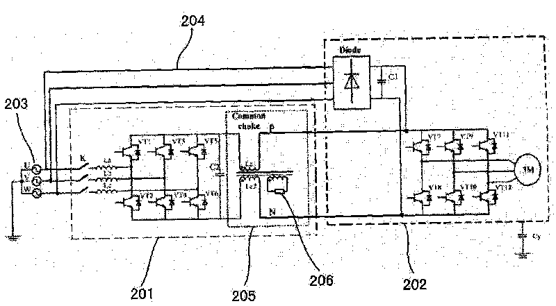
[0026] see figure 2 , the circuit includes an energy feedback circuit 201 , a frequency converter circuit 202 , a three-phase grid 203 and a DC bus 204 in the existing structure. A common-mode inductor 205 with damping resistance is connected in series between the feeder circuit and the inverter circuit. The common-mode inductor is connected to the DC bus side of the feeder and has a three-phase common-core structure, two of which are connected to the feeder P , N incoming line terminal, another phase is connected in series with a damping resistor 206, and the damping resistor is connected to an independent winding with a common core of the common mode inductor. The improved circuit can reduce the common mode interference caused by the feedback device to the system when the feedback device is working.

Embodiment 2

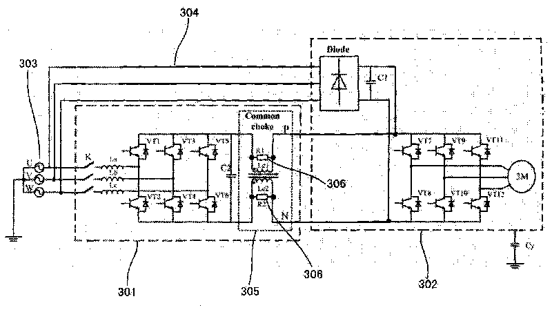
[0028] see image 3 , the circuit includes an energy feedback circuit 301 , a frequency converter circuit 302 , a three-phase grid 303 and a DC bus 304 in the existing structure. A common mode inductor 305 with a damping resistor is connected in series between the feedback circuit and the frequency converter circuit. The common mode inductor is connected to the DC bus side of the feedback device and has a two-phase common core structure. The two damping resistors 306 are directly connected in parallel. Connected to both ends of each winding of the two-phase winding of the common mode inductor. The improved circuit can reduce the common mode interference caused by the feedback device to the system when the feedback device is working.

Embodiment 3

[0030] see Figure 4 , the circuit includes an energy feedback circuit 401 , a frequency converter circuit 402 , a three-phase grid 403 and a DC bus 404 in the existing structure. A common-mode inductor 405 with a damping resistor is connected in series between the three-phase grid and the feeder circuit. The common-mode inductor is connected to the grid side and has a four-phase common-core structure. A damping resistor 406 is connected in series with the other phase, and the damping resistor is connected to an independent winding with a common core of the common mode inductor. The improved circuit can reduce the common mode interference caused by the feedback device to the system when the feedback device is working.


PUM


Abstract

The invention discloses a circuit structure for common-mode inductors with damping resistors applied to energy feedback devices. The circuit consists of an energy feedback device circuit consisting of a filter reactor and a feedback device inverting bridge, a frequency converter circuit consisting of a motor and a frequency converter inverting bridge, a DC bus and a three-phase power network group, wherein common-mode inductors with damping resistors are connected in series between the three-phase power network and the feedback device circuit connected with the three-phase power network or between the feedback device circuit and the frequency converter circuit connected with the feedback device circuit. The common-mode inductors in the circuit structure can effectively suppress common-mode current and reduce EMI interference so as to allow the application range of feedback devices to be wider. Through common-mode chokes designed, the energy feedback devices applying the circuit structure can allow resonance frequency points of common-mode current of main loops to be far from power-tube switching frequency, and the additional damping resistors can greatly reduce the common-mode current near resonance points so as to reduce common-mode interference caused by the work of the feedback devices and allow the feedback devices to be wider in application range and higher in reliability.

Description

Technical field: [0001] The invention relates to the application field of driving potential energy loads such as elevators, in particular to a common-mode inductance circuit structure with damping resistance applied in an energy feedback device. Background technique: [0002] Nowadays, most energy feedback devices on the market adopt PWM (Pulse Width Modulation, pulse width modulation) control technology, which inevitably makes the three-phase output voltage of the feedback device generate high-frequency common-mode voltage, thereby causing common-mode current. If the feedback If the inverter does not take common mode interference suppression measures, it will not only directly affect its application in the electric drive system (not only used in elevators), but also affect the normal operation of other equipment. [0003] When the DC bus side of the inverter is connected to the ground with a Y capacitor ( figure 1 In Cy), after installing a general energy feedback device, ...

Claims


Application Information

Patent Timeline
Patent Type & Authority Applications(China)
IPC IPC(8): H02J3/38H02M3/335H01F17/04H01F27/40
Inventor 吴志敢王微子赵小安魏冬冬李锦庚
Owner SHANGHAI GIE EM
Why Eureka
Try Eureka