Powder metal forging and method and apparatus of manufacture

一种粉末金属、锻件的技术,应用在金属加工设备、机械设备、车辆部件等方向,能够解决昂贵加工设置、模具寿命短、复杂等问题,达到小化材料浪费、减少模具成本、接触的时间最小化的效果

Inactive Publication Date: 2010-05-19
GKN SINTER METALS GMBH & CO KG
View PDF0 Cites 2 Cited by
  • Summary
  • Abstract
  • Description
  • Claims
  • Application Information

AI Technical Summary

Problems solved by technology

Other disadvantages of this method are that the method is a rather complex and expensive tooling setup with a relatively short die life

Method used


Image

  • Powder metal forging and method and apparatus of manufacture
  • Powder metal forging and method and apparatus of manufacture
  • Powder metal forging and method and apparatus of manufacture

Examples


Embodiment Construction

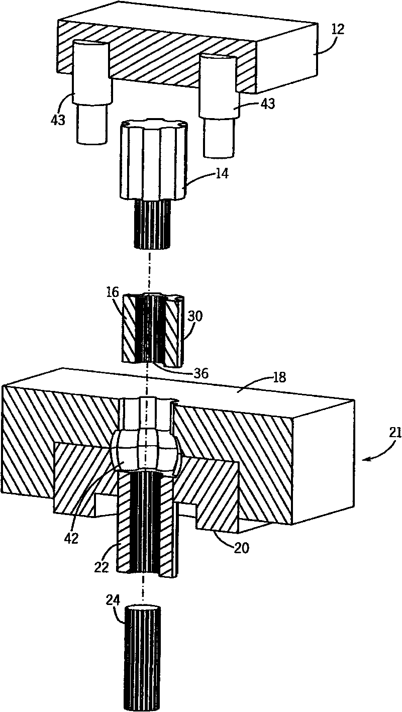
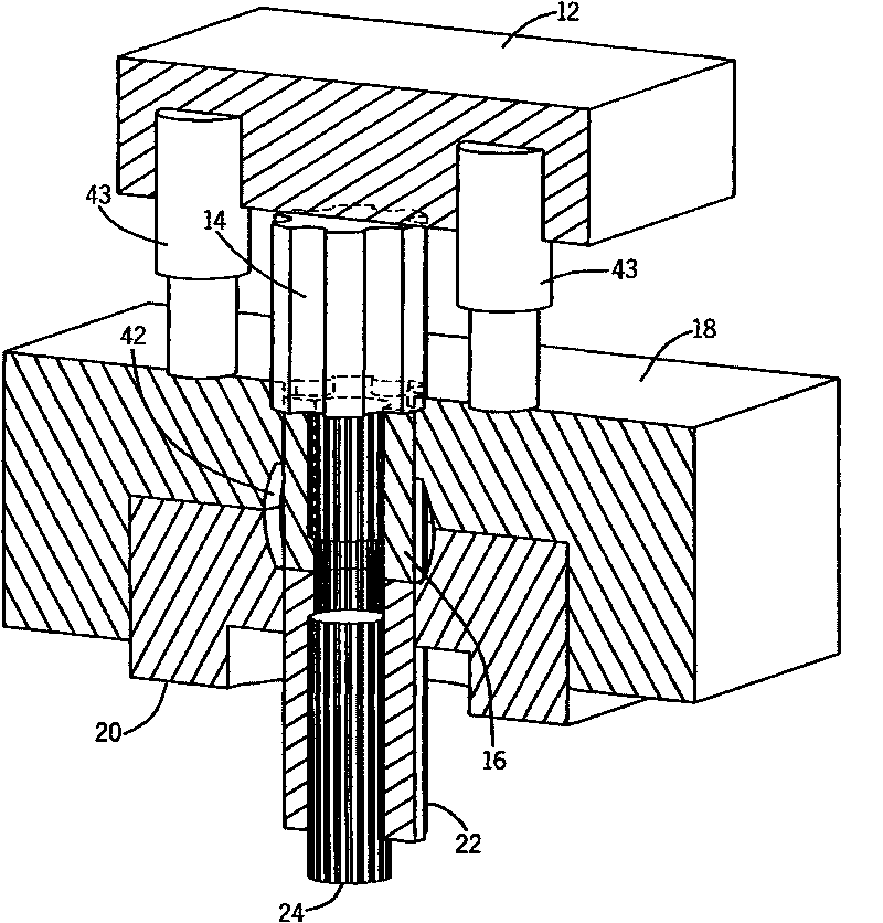
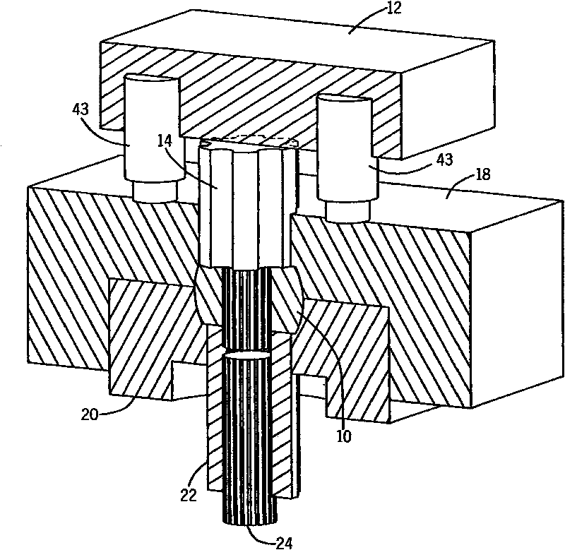
[0030] See now the accompanying drawings, especially figure 1 , Image 6 and Figure 7 , which illustrate a method and apparatus for forming a powder metal forging 10, which may include a ram or hammer 12, an upper punch 14, a preform 16, an upper die 18 and a lower die 20 forming a die set 21, a lower die Punch 22 and snag pin 24 .

[0031] See especially Image 6 , the preform 16 comprises a powdered metal composition that has been compacted and subsequently sintered. The composition of the powder metal includes nickel between about 0.40% and 2.00%, molybdenum between about 0.50% and 0.65%, manganese between about 0.10% and 0.35%, manganese between about 0.12% and 0.80% Between carbon, and the balance iron. The preform 16 is a non-cylindrical preform that includes a first end 26 , a second end 28 opposite the first end, and an outer profile 30 connecting the first end 26 and the second end 28 . The outer profile 30 comprises a plurality of longitudinal protrusions 32 a...


PUM

PropertyMeasurementUnit
densityaaaaaaaaaa
densityaaaaaaaaaa

Abstract

A method of forming a powder metal forging, including the steps of: forming a preform including a sintered powder metal composition; inserting the preform in a die set having a bottom die and a top die, the die set defining a forge form therewithin, the die set being in a closed position wherein the top die is contacting the bottom die; and compressing the preform in the forge form using an upper punch and a lower punch, the compressing step resulting in a formed part. The closed die set minimizes or eliminates flash in the formed part, particularly in the contoured surfaces, which allows the forging to be through hardened by direct quenching after the forging operation, without the need to remove hardened flash from these surfaces.

Description

[0001] Cross References to Related Applications [0002] This application claims priority to US Provisional Patent Application No. 60 / 900,893, filed February 12, 2007, which is incorporated herein by reference. Statement Regarding Federally Funded Research [0003] Not applicable technical field [0004] The present invention relates to powder metal forgings, and more particularly to powder metal forgings with minimal or no flash / precise flash. Background technique [0005] In the manufacture of powder metal forgings such as inner races of constant velocity joints (CVJs), it is sometimes desirable to provide hardened parts directly from the forging process. This necessitates quenching the part directly after exiting the forging tool. During the forging of such parts, the upper die is moved in a downward direction to the lower die to deform the blank to form the part. This results in flash forming on the side of the part at the punch and die junction, which for the inner ...

Claims


Application Information

Patent Timeline
Patent Type & Authority Applications(China)
IPC IPC(8): B22F3/00C22C1/00
CPCB22F5/08B21J5/12B22F2003/175B22F3/17B21K1/30C22C1/00B21K1/762C22C33/0264B21J5/025B21J5/002B21K1/763Y10T428/12014
Inventor 阿尔弗雷德·J·奇萨小大卫·E·伦哈特
Owner GKN SINTER METALS GMBH & CO KG
Why Eureka
Try Eureka