Machining method of semi-rigid cable part

A processing method and semi-rigid technology, applied in metal processing equipment, manufacturing tools, pipe shearing devices, etc., can solve the problems of low production efficiency, poor straightness, high scrap rate, etc., and achieve improved production efficiency, convenient use, and stable quality Effect

Active Publication Date: 2012-09-26
BEIJING RES INST OF TELEMETRY +1
View PDF0 Cites 0 Cited by
  • Summary
  • Abstract
  • Description
  • Claims
  • Application Information

AI Technical Summary

Problems solved by technology

The traditional processing method is to remove the outer layer of copper with an outer circular turning tool. Since the interlayer of the part is a non-metallic material, the outer metal layer is only 0.1-0.5mm. Because the part is slender, soft, and poor in straightness, the conventional method When removing the metal layer, there are obvious marks on the surface of the non-metal layer, causing the parts to bend, jump and deform
The production efficiency is low, the scrap rate is high, and it is difficult to meet the accuracy requirements of the design drawings

Method used


Image

  • Machining method of semi-rigid cable part
  • Machining method of semi-rigid cable part
  • Machining method of semi-rigid cable part

Examples


Embodiment Construction

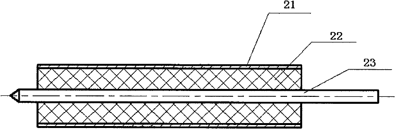
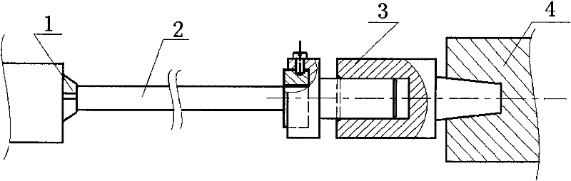
[0018] The feeder structure of the parts in this embodiment is as follows: figure 1 As shown, the semi-rigid cable material is used, and the part material is composed of three parts: metal copper tube 21, non-metal interlayer 22, and metal copper core 23. It is a composite flexible material with a maximum length-to-diameter ratio of up to 60. Drawing processing requires that after removing the metal copper tube 21, it becomes the required part feeder.

[0019] Present embodiment adopts processing method of the present invention to be:

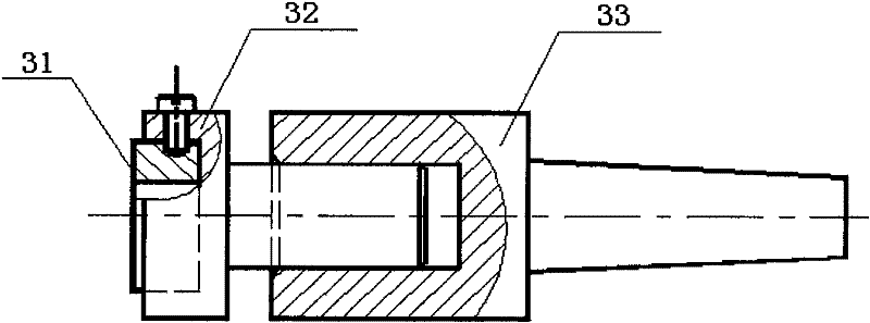
[0020] The first step is to design a special threaded sleeve such as figure 2 As shown, the special-purpose threaded sleeve 3 includes a die 31, a die locking sleeve 32 and a taper sleeve 33. The die 31 is a tool for processing external threads, among which the circular die is the most widely used, and the specification range is M0.25 ~M68mm. There are national standards for round dies and hexagonal dies, and their sizes are used in conjunct...


PUM


Abstract

The invention discloses a machining method of a semi-rigid cable part, and the method comprises the following steps: 1. designing a dedicated thread sleeve, wherein the dedicated thread sleeve comprises a threading die, a threading die lock sleeve and a taper sleeve; when the dedicated thread sleeve is used, the threading die is put into the front end of the threading die lock sleeve and is locked by virtue of bolts; a round hole on the front end of the taper sleeve and the optical axis of the rear end of the threading die lock sleeve are matched; the angle of the taper shank of the rear end of the taper sleeve is matched with the conical degree of a machine tool tailstock; 2. putting the semi-rigid cable part into a lathe spindle clamping tank to expose required machining length; 3. putting the taper sleeve into the machine tool tailstock, clamping the threading die by the lock sleeve, pushing the machine tool tailstock to cause the threading die to be cut into the part, manually sheathing threads, and stopping machining on the position 3-5mm in front of the part; 4. cutting a scratch of which the depth is 0.15mm on a circumferential surface with the required machining length by virtue of a cutter; 5. slightly rocking the handwheel of the machine tool tailstock; and causing the metal copper tube of the cable part to be totally separated from a non-metal sandwich by the part under the acting force of the axial tension force of the dedicated thread sleeve so as to finish machining the semi-rigid cable part.

Description

technical field [0001] The invention relates to a processing method of cable parts, which is especially applied in the processing of semi-rigid cables made of composite flexible materials, and can be popularized and used in other rotary parts of similar materials. Background technique [0002] Semi-rigid cables consist of composite flexible materials. The traditional processing method is to remove the outer layer of copper with an outer circular turning tool. Since the interlayer of the part is a non-metallic material, the outer metal layer is only 0.1-0.5mm. Because the part is slender, soft, and poor in straightness, the conventional method When the metal layer is removed, there are obvious traces of the knife on the surface of the non-metal layer, causing the parts to bend, jump and deform. The production efficiency is low, the scrap rate is high, and it is difficult to meet the accuracy requirements of the design drawings. Contents of the invention [0003] The techn...

Claims


Application Information

Patent Timeline
Patent Type & Authority Patents(China)
IPC IPC(8): B23D21/00
Inventor 朱景林李维静
Owner BEIJING RES INST OF TELEMETRY
Why Eureka
Try Eureka