Rewinding roller structure used in toilet paper rewinding machine and rewinding method thereof

A toilet paper roll and rewinding roll technology, which is applied in the field of paper product processing, can solve the problems affecting the bulkiness and softness of toilet paper products, pattern deformation, and poor hand feeling, and achieve good hand feeling effect, good bulkiness and softness High degree of practicality and strong effect

Inactive Publication Date: 2010-05-26
陆德昌
View PDF0 Cites 6 Cited by
  • Summary
  • Abstract
  • Description
  • Claims
  • Application Information

AI Technical Summary

Problems solved by technology

[0002] The structure of the rewinding roller in the existing toilet paper rewinding machine generally includes an upper rewinding roller, a lower rewinding roller, a rear rewinding roller and its pressure roller. It can be attached to the rear rewinding roller to avoid slipping, loosening and shifting to affect the breaking effect, so as to ensure the continuous reliability of its work and make the breaking line of the base paper on the same perforation line. The roller needs to be pressed with the rear rewinding roller for a long time, so that the toilet paper passing between the rear rewinding roller and the pressure roller will be squeezed, so that the patterned toilet paper will be squeezed during the production process. The problem of deformation will seriously affect the bulkiness and softness of the finished toilet paper with patterns, resulting in poor hand feeling.

Method used


Image

  • Rewinding roller structure used in toilet paper rewinding machine and rewinding method thereof
  • Rewinding roller structure used in toilet paper rewinding machine and rewinding method thereof
  • Rewinding roller structure used in toilet paper rewinding machine and rewinding method thereof

Examples


Embodiment Construction

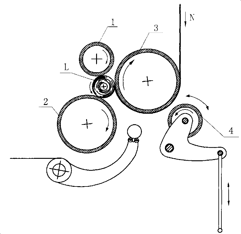
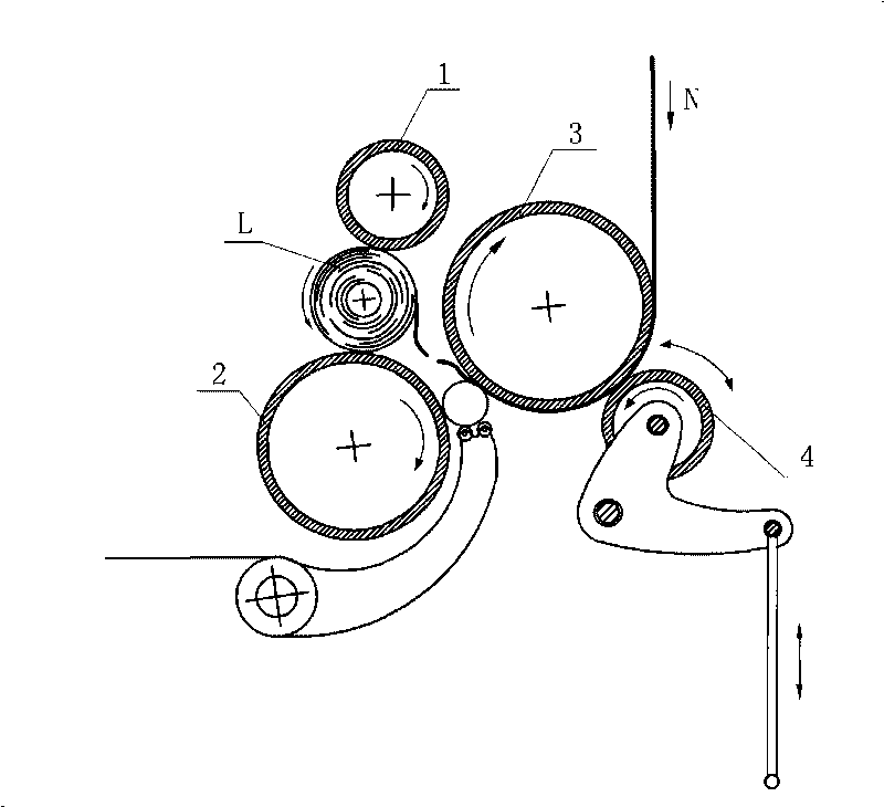
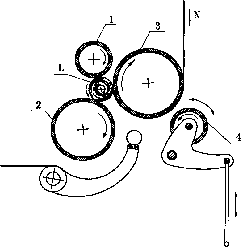
[0016] like Figure 1 to Figure 2 As shown in the figure, a rewinding roller structure for a toilet paper rewinding machine according to the present invention includes an upper rewinding roller 1, a lower rewinding roller 2, a rear rewinding roller 3 and a rear rewinding roller 3 installed in sequence. The roller 3 has a pressing roller 4 with the same linear speed, wherein the pressing roller 4 opens and closes with the rear rewinding roller 3 in a timely manner through the drive of a driving mechanism during the rewinding of the base paper and the speed-up of the upper rewinding roller 1 to break the base paper. ground contact. Wherein, the above-mentioned driving mechanism is an air cylinder or a synchronous cam or a servo motor.

[0017] A rewinding method for a toilet paper rewinding machine according to the present invention comprises the following steps:

[0018] (1) A pressing roller 4 that can be opened and closed with the rear rewinding roller 3 and has the same li...


PUM


Abstract

The invention provides a rewinding roller structure used in a toilet paper rewinding machine and a rewinding method thereof. The rewinding roller structure comprises an upper rewinding roller, a lower rewinding roller, a rear rewinding roller and a compression roller which are installed in sequence, wherein the compression roller has the same linear speed with the rear rewinding roller. The rewinding roller structure is characterized in that the compression roller is contacted with the rear rewinding roller in an opening and closing manner duly by the driving of a driving mechanism in the process of the rewinding of the base paper and the base paper being snapped when the upper rewinding roller speeds up. As the invention adopts the structure that the compression roller can be contacted with the rear rewinding roller in an opening and closing manner, the compression roller does not contact with the rear rewinding roller when the patterned toilet paper performs normal rewinding, thus ensuring that the patterned toilet paper is not deformed, leading the finished products thereof to possess good bulking intensity and flexibility, and ensuring good handfeel effect of users; when the upper rewinding roller performs paper snapping by speeding up, the compression roller is compressed with the rear rewinding roller duly, ensuring the accuracy and reliability of the cutting of the toilet paper and the continuity of the work; and the invention is also characterized by simple and smart structure and applicability and reliability.

Description

technical field [0001] The invention relates to the technical field of paper product processing, in particular to a rewinding roller structure for a toilet paper rewinding machine and a rewinding method thereof. Background technique [0002] The structure of the rewinding roller in the existing toilet paper rewinding machine generally includes an upper rewinding roller, a lower rewinding roller, a rear rewinding roller and a pressing roller thereof. It can be attached to the rear rewinding roller to avoid slipping, loosening and displacement, which will affect the breaking effect, so as to ensure the continuous reliability of its work and the breaking line of the base paper to be located on the same punching line. The roller needs to be pressed with the rear rewinding roller for a long time, so that the toilet paper passing between the rear rewinding roller and the pressing roller will be squeezed, so that the patterned toilet paper will be squeezed during this production pr...

Claims


Application Information

Patent Timeline
Patent Type & Authority Applications(China)
IPC IPC(8): B65H18/16B65H19/26B65H19/30
Inventor 陆德昌
Owner 陆德昌
Why Eureka
Try Eureka