Four-point support of quadrilateral subpanel based universal detection method of radio telescope

A radio telescope and four-point support technology, which is applied to measurement devices, instruments, optical devices, etc., can solve the problems of heavy workload of batch real-time detection, inability to detect real-time radio telescopes and ensure surface accuracy, etc. Clear, simple structure, and the effect of reducing labor intensity

Inactive Publication Date: 2010-05-26
NANJING INST OF ASTRONOMICAL OPTICS & TECH NAT ASTRONOMICAL OBSE
View PDF0 Cites 25 Cited by
  • Summary
  • Abstract
  • Description
  • Claims
  • Application Information

AI Technical Summary

Problems solved by technology

[0006] The common disadvantage of the above radio telescope reflective surface detection methods is that it is only suitable for the detection and review of reflective surfaces at a single or certain height positions, and it is impossible to detect and ensure that the calibrated surface after the installation and adjustment of the radio telescope is real-time during the working process of the radio telescope. shape accuracy, the workload of batch real-time detection is particularly heavy

Method used


Image

  • Four-point support of quadrilateral subpanel based universal detection method of radio telescope
  • Four-point support of quadrilateral subpanel based universal detection method of radio telescope
  • Four-point support of quadrilateral subpanel based universal detection method of radio telescope

Examples


Embodiment 1

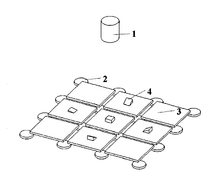
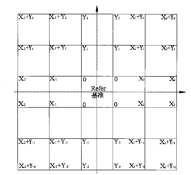
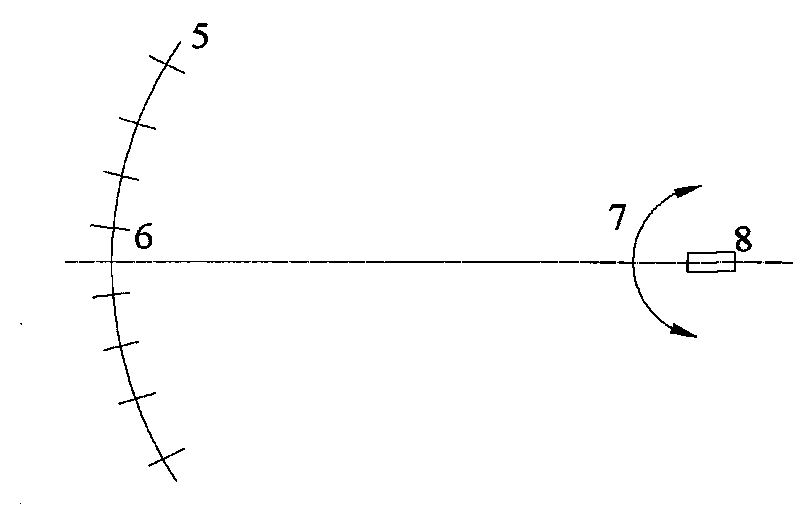
[0036] Embodiment 1, based on the real-time radio telescope splicing common phase detection method based on the four-point support of the quadrilateral sub-panel, in figure 1 Among them, the antenna detection system includes a laser scanning system 1, a four-point support 2 for each panel, a quadrilateral panel to be detected 3 and a target system 4; figure 2 with image 3 The two laser scanning systems correspond to single laser and multi-laser beam systems respectively, where image 3 Including: splicing antenna 5, laser emission 6, high-precision rotating scanning target surface support mechanism 7, target surface 8 and adjustable plane mirror target 9; Figure 5 with Image 6 There are two splicing target surface design schemes respectively, Image 6 Designed for simplified target surfaces in two scanning directions.

[0037] The rotatable tracking and scanning target surface system fixed at the center of curvature, the laser and target system can be a system with onl...

Embodiment 2

[0038] Embodiment 2 is basically the same as Embodiment 1, but said step (1), step (2) and step (3) are replaced by: (1). Target is placed on a sub-panel of a diameter in the center of the antenna; (2 ).Scanning along the oblique direction, only need to scan the orientation of a diameter, each panel can solve (Xi, Yi) at the same time; (3).Through the image spot position of the mosaic target surface which is translated and rotated together with the laser reflection device The measurement information is processed to obtain angular data for a diameter.


PUM


Abstract

The invention relates to a four-point support of quadrilateral subpanel based universal detection method of a radio telescope, comprising the following steps of: (1) arranging a target on at least one entire line of subpanels and at least one entire row of the subpanels which are positioned in the center of an antenna; (2) at least scanning the targets arranged on one entire line of the subpanels and one entire row of the subpanels which are positioned in the center of the antenna by a high-precision rotational tracking scanning laser receiving device or a laser emitting and receiving device; recording the positions of the laser emitting device aiming at different targets by a high-precision coder; (3) obtaining angle data by measuring the information of the image patch position of a spliced target surface which translates and rotates along with the laser emitting device; and (4) directly educing the positional deviation of all panels, the surface shape precision of the integral spliced antenna and supporting point displacement needed by correcting the surface shape precision, i.e. the correction of a promoter. Aiming at the radio telescope, the paraboloid antenna adopts the design based on the four-point support of the quadrilateral subpanel and realizes the real-time splicing detection and the regulation of batched panels at low manufacturing cost through simple and easy process.

Description

technical field [0001] The invention relates to a method for splicing and co-phase detection and correction of radio telescopes based on four-point support of quadrilateral sub-panels, which is very suitable for splicing and co-phase detection and correction of radio panels of radio telescopes and millimeter / submillimeter wave telescopes. Background technique [0002] A radio telescope usually has a large aperture, and its antenna (main panel) is usually spliced ​​by a large number of small panels. For example, a 65-meter-caliber radio telescope antenna is composed of thousands of one-meter panels. During the formal operation, under the influence of external loads such as gravity and wind, it is necessary to ensure that the overall surface shape of the paraboloid is within the allowable range. In addition to considering the conformal design of the support of the antenna back frame, the splicing inspection of large quantities of panels is also a key part of the design and ope...

Claims


Application Information

Patent Timeline
Patent Type & Authority Applications(China)
IPC IPC(8): G01B11/24
Inventor 张勇杨德华李烨平
Owner NANJING INST OF ASTRONOMICAL OPTICS & TECH NAT ASTRONOMICAL OBSE
Why Eureka
Try Eureka