Motor

A technology of motors and bearings, applied in the field of motors that are easy to assemble, can solve the problem that the bearings cannot provide enough deformation space, so as to improve the convenience of assembly and ensure the effect of product quality

Active Publication Date: 2010-05-26
SUNONWEALTH ELECTRIC MACHINE IND
View PDF1 Cites 4 Cited by
  • Summary
  • Abstract
  • Description
  • Claims
  • Application Information

AI Technical Summary

Problems solved by technology

[0005] The main purpose of the present invention is to provide a motor, which is mainly used to solve the problem that the bearing of the existing motor cannot provide enough deformation space and the like

Method used


Image

  • Motor
  • Motor
  • Motor

Examples


Embodiment Construction

[0033] In order to allow the above-mentioned and other objects, features and advantages of the present invention to be more clearly understood, the preferred embodiments of the present invention will be specifically cited below, together with the accompanying drawings, and described in detail as follows:

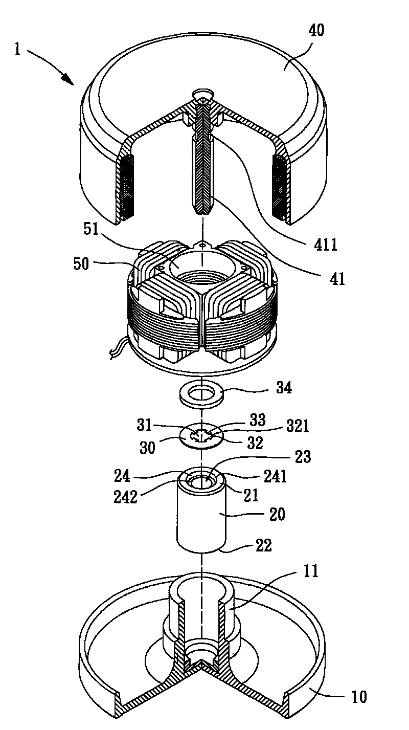
[0034] Please refer to image 3 and Figure 4 As shown, the motor 1 of the first embodiment of the present invention at least includes a base 10 , a bearing 20 , a positioning member 30 , a rotor 40 and a stator 50 . in:

[0035] The base 10 has a shaft tube 11 , one end of the shaft tube 11 is closed, and the other end is opened, for assembling the bearing 20 , the positioning member 30 and other related components.

[0036] The bearing 20 is disposed in the shaft tube 11, the bearing 20 has a first end surface 21 and a second end surface 22, and the bearing 20 is further provided with a through hole 23, the through hole 23 runs through the first end surface 21 to the On...


PUM


Abstract

The invention relates to a motor comprising a base, a bearing, a positioning piece, a rotor and a stator. The base is provided with a shaft tube; the bearing is arranged in the shaft tube and provided with a through hole and a concave part having an axial direction; the positioning piece is combined with the bearing, provided with a perforation and a plurality of grooves and has a radial direction from the inner hole wall of the perforation to the inner hole wall of the through hole of the bearing, wherein the radial direction is no more than the axial direction; the rotor is provided with a rotating shaft which is combined with the through hole of the bearing; and the stator is sleeved on the outer peripheral surface of the bearing. Accordingly, the invention can utilize the concave part of the bearing to provide the positioning piece with an enough deformation space, thereby facilitating the assembly operation of the rotor and the positioning piece and effectively preventing the positioning piece from being damaged in the assembly process.

Description

technical field [0001] The present invention relates to a motor, in particular to a motor which facilitates assembly work. Background technique [0002] Existing motors, such as China Taiwan Application No. 94147553 "Motor Rotor Structure" invention patent case please refer to figure 1 As shown, the conventional motor 9 generally includes a housing 91 , a stator 92 , a rotor 93 , a retaining ring 94 and a collar 95 . The casing 91 has a base wall 911, and a shaft tube 912 is arranged on the base wall 911, and a bearing 913 is arranged inside the shaft tube 912; the stator 92 is sleeved on the outer peripheral wall of the shaft tube 912; the rotor 93 has a Shaft 931, the shaft 931 is combined with the bearing 913, and the peripheral wall of the shaft 931 is provided with a buckle groove 932; the buckle 94 can be formed as figure 2 As shown in the closed ring structure, the clasp 94 has a central hole 941 and several notches 942 extending outward from the central hole 941 ;...

Claims


Application Information

Patent Timeline
Patent Type & Authority Applications(China)
IPC IPC(8): H02K5/167H02K7/08
Inventor 洪银树
Owner SUNONWEALTH ELECTRIC MACHINE IND
Why Eureka
Try Eureka