Method for dissipating heat of thermotube of convertor and radiator thereof

A technology of heat pipe radiator and converter, which is applied in the direction of cooling/ventilation/heating transformation, output power conversion device, electrical components, etc. It can solve the problems of welding quality influence and low efficiency, and achieve excellent heat dissipation performance and total heat dissipation. The effect of reducing the resistance and changing the insufficient heat dissipation area

Active Publication Date: 2010-05-26
SHIDAI ELECTRIC FACTORY ZHUZHOU ELECTRIC LOCOMOTIVES INST MIN OF RAILWAYS +1
View PDF0 Cites 4 Cited by
  • Summary
  • Abstract
  • Description
  • Claims
  • Application Information

AI Technical Summary

Problems solved by technology

However, when it is applied to multiple thyristors or IGBT modules, or the power loss is greater than 3000W, not only the efficiency will be low, but also the welding quality will affect the contact thermal resistance R3, and the thermal resistance R2 of the soldering layer itself is also unavoidable. In this way, the total heat If the resistance is equal to the sum of all thermal resistances, it cannot be reduced.

Method used


Image

  • Method for dissipating heat of thermotube of convertor and radiator thereof
  • Method for dissipating heat of thermotube of convertor and radiator thereof
  • Method for dissipating heat of thermotube of convertor and radiator thereof

Examples


Embodiment Construction

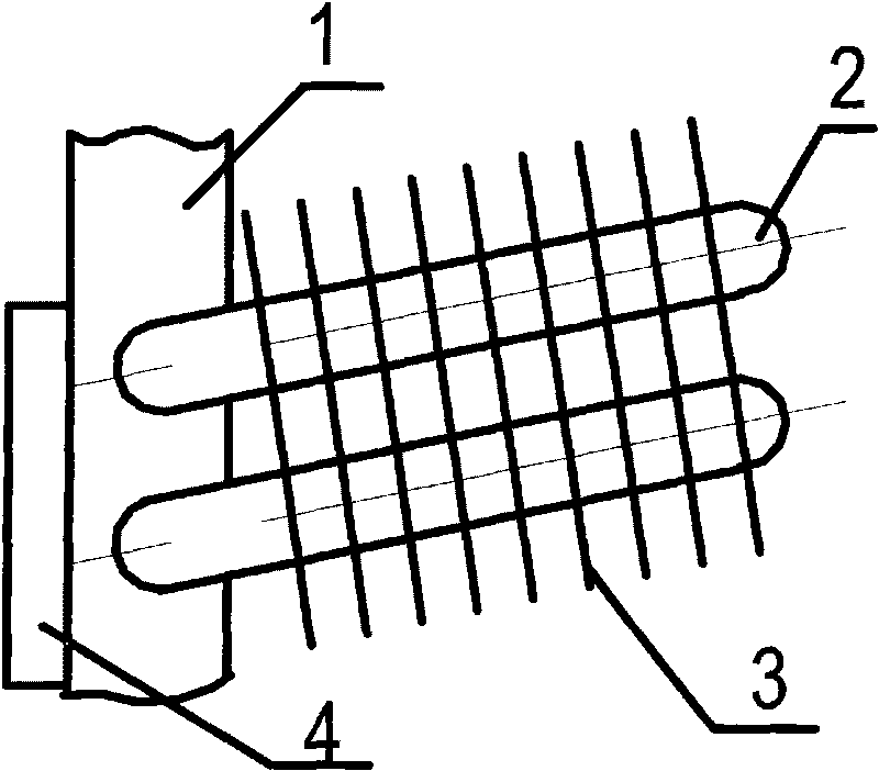
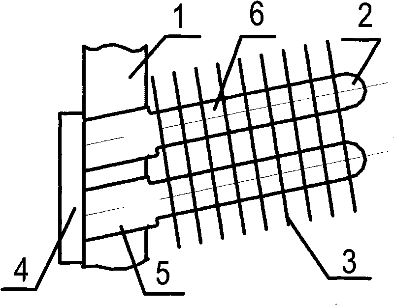
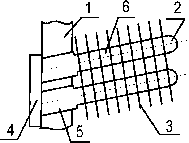
[0014] attached figure 2 An embodiment of the present invention is given, and the present invention will be further described below in conjunction with the accompanying drawings.

[0015] From attached figure 2 It can be seen from the figure that the present invention is a converter heat pipe radiator, which adopts heat pipes to dissipate heat. Insert straight and obliquely into the main plane of the radiator substrate and pass through the substrate. The bottom surface of the root of the heat pipe directly contacts the surface of the heat-generating substrate of the converter; and the cross-section of the heat pipe changes, which is a stepped structure with a small top and a large bottom. The cross-section is larger than that of the upper part, and the heat dissipation of the converter heating substrate is directly conducted through the bottom surface of the root of the heat pipe which is in direct contact with the surface of the converter heating substrate.

[0016] The c...


PUM


Abstract

The invention relates to a method for dissipating heat of a thermotube of a convertor and a radiator thereof. The thermotube is adopted to dissipate heat and inserted into a baseplate of the radiator; the baseplate of the radiator clings to a heating baseplate of the convertor; the thermotube is vertically and obliquely inserted into a main plane of the baseplate of the radiator and runs through the baseplate; the underside of the root of the thermotube is directly contacted with the surface of the heating baseplate of the convertor; the cross section of the thermotube is variable and the thermotube has a ladder-shaped structure of which the upper part is small and the lower part is large; the section of the root is larger than that of the upper part; and the heat of the heating baseplate of the convertor is directly conducted out through the underside of the root of the thermotube directly contacted with the surface of the heating baseplate of the convertor. The radiator comprises a radiator baseplate, the thermotube, a radiating fin and the heating baseplate of the convertor; the root of the thermotube is vertically and obliquely inserted into the main plane of the baseplate of the radiator and passes through the baseplate; the underside of the root of the thermotube is directly contacted with the surface of the heating baseplate of the convertor; and the thermotube has the ladder-shaped structure of which the upper part is small and the lower part is large. Compared with that of the conventional radiator, the entire thermal resistance of the radiator can be reduced by 20 to 30 percent; and the heat dissipation power is increased by 100 percent.

Description

technical field [0001] The invention relates to a heat dissipation method for electric power equipment and its heat dissipation device, in particular to a heat pipe heat dissipation method for a converter of electric power equipment and its radiator. The international patent classification number is B61F05 / 02, which is mainly used for various rails. Large-capacity radiators for traffic (electric power, diesel locomotives, EMUs and subway vehicles, etc.) converters or other power equipment converters. Background technique [0002] When rail transit vehicles (electric power, diesel locomotives and subway vehicles) and power equipment converters work, power loss (heat) will be generated, so heat dissipation is required. The greater the power consumption, the greater the heat dissipation capacity. At present, the heat dissipation methods of converters mainly include air cooling, water cooling and heat pipe cooling. Only heat pipe radiators and water cooling have large-capacity h...

Claims


Application Information

Patent Timeline
IPC IPC(8): H02M1/00H05K7/20
Inventor 朱继贤李春阳李纯廖向前
Owner SHIDAI ELECTRIC FACTORY ZHUZHOU ELECTRIC LOCOMOTIVES INST MIN OF RAILWAYS
Why Eureka
Try Eureka