
Heating mechanism of asphalt pavement heater

A technology for asphalt pavement and heating mechanism, which is applied to roads, roads, road repair and other directions, can solve problems such as aggravating gas waste, increasing consumption of liquefied gas, wasting energy, etc., to improve construction speed, increase heating area, and save energy. Effect

Inactive Publication Date: 2010-06-02
CHANGSHU GAOSIDA INSTR EQUIP
View PDF7 Cites 16 Cited by
  • Summary
  • Abstract
  • Description
  • Claims
  • Application Information

AI Technical Summary

Problems solved by technology

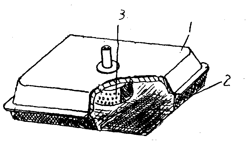
In view of this, the heating mechanism involved in CN2856135Y is not conducive to saving energy and is not enough to improve the heating effect of the overall heating of the asphalt pavement corresponding to the underside of the steel wire mesh 2, because the burner 3 is arranged in the shell cavity of the shell cover 1 In the center, when the burner 3 is working (burning), the temperature of the asphalt pavement corresponding to the area below the burner 3 rises quickly, reaching a repaired pavement temperature of about 160°C, but the temperature of the pavement far away from the burner 3 It often takes a long time to reach the temperature suitable for repairing, thus increasing the consumption of liquefied petroleum gas, prolonging the heating time of the road surface, and affecting the construction progress
If the volume of the burner 3 is increased so that the area corresponding to the road increases, but such selection will further aggravate the waste of gas, and it still does not help to improve the construction speed; again, if the number of the burner 3 is increased, For example, burners 3 are respectively arranged at the four corners and the center of the shell cover 1, which not only leads to a complicated structure, but also wastes more energy.

Method used


Image

  • Heating mechanism of asphalt pavement heater
  • Heating mechanism of asphalt pavement heater
  • Heating mechanism of asphalt pavement heater

Examples


Embodiment Construction

[0020] In order to enable the examiners of the patent office, especially the public, to understand the technical essence and beneficial effects of the present invention more clearly, the applicant will describe in detail below in conjunction with the accompanying drawings in the form of embodiments, but none of the descriptions of the embodiments is a description of the present invention. Restriction of the inventive solution, any equivalent transformation made according to the concept of the present invention which is only in form but not in substance shall be regarded as the scope of the technical solution of the present invention.

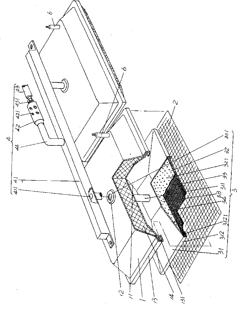
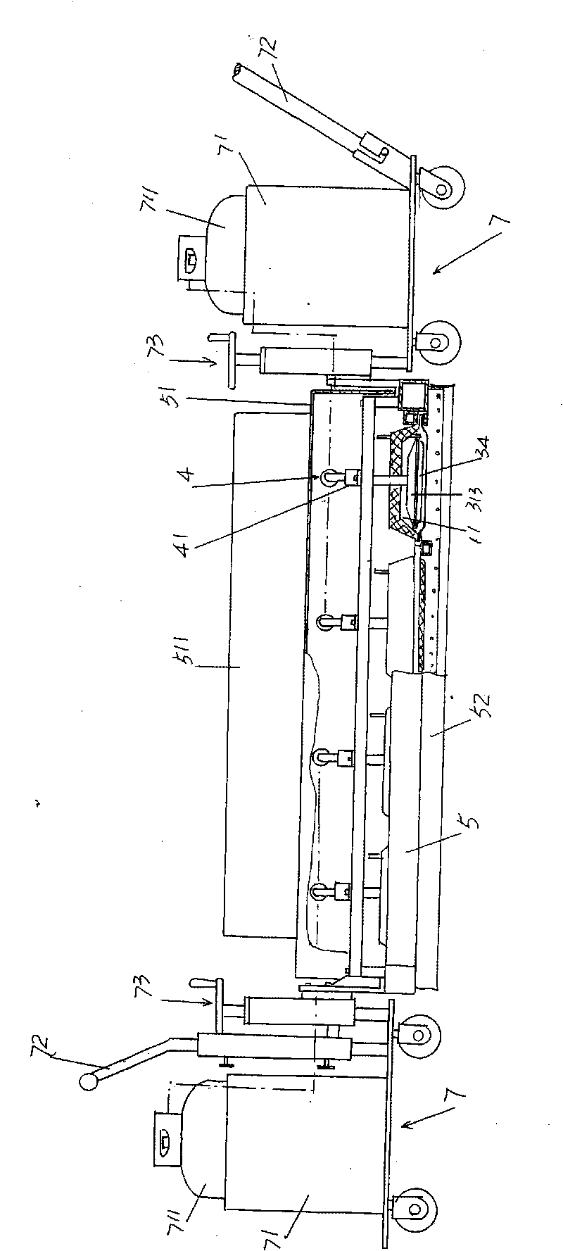
[0021] Please see figure 1 ,exist figure 1 Although the applicant only provided two sets of heating mechanisms, it is obviously not limited by the number shown in the figure. When there are two or more groups, the air-entraining device 4 does not need to be increased by the same amount. For example, one air-entraining device 4 can simultaneous...


PUM


Abstract

The invention relates to a heating mechanism of an asphalt pavement heater, belonging to the technical field of road maintenance facilities. The heating mechanism comprises a shell cover provided with a shell cover cavity, a combustor arranged inside the shell cover cavity, a steel wire gauze which is fixed at the bottom of the shell cover and corresponds to the lower part of the combustor, and an air-entraining device that is connected on the shell cover and communicated with the combustor. The heating mechanism is characterized in that the combustor comprises a gas cover provided with a diversion cavity, a spreader plate which is distributed with vent holes on a plate body, and a thermal radiation net, wherein the middle part of the gas cover is extended with an air feed pipe which is connected with the air-entraining device; the spreader plate and the thermal radiation net are respectively fixed with the bottom of the gas cover; the thermal radiation net corresponds to the lower part of the spreader plate, and a combustion cavity is formed between the thermal radiation net and the spreader plate; and the vent holes are communicated with the combustion cavity. By improving the structure of the combustor in the prior art, the heating mechanism enlarges the heating area for asphalt pavement, thus not only saving energy, but also accelerating the construction speed.

Description

technical field [0001] The invention belongs to the technical field of road maintenance facilities, and in particular relates to a heating mechanism of an asphalt pavement heating machine. Background technique [0002] After a period of use on the asphalt pavement, damage phenomena such as potholes and scattered cracks often appear, and maintenance repairs must be carried out in time, otherwise the potholes and cracks will gradually expand, causing difficulties in repair. In the prior art, the repair of potholes and scattered cracks often adopts the oil bag repair method. This repair method has the advantages of high work efficiency and material saving. However, it is difficult to form a good affinity between the injected oil bag and the original asphalt. Compatibility, so shelling occurs, resulting in a high repair rate. In order to have a good or friendly bonding effect between the newly added asphalt and the original roadbed asphalt, it is necessary to plan the road surf...

Claims


Application Information

Patent Timeline
IPC IPC(8): E01C23/06E01C23/14
Inventor 戴叙生戴建斌戴丽娟
Owner CHANGSHU GAOSIDA INSTR EQUIP
Learn More