
Spherical magnetorheological fluid clutch

A magneto-rheological fluid and clutch technology, applied in the field of clutches, can solve the problems of occasions that are not on the same straight line or have a certain angle, and achieve the effect of not easy to leak and compact structure

Inactive Publication Date: 2010-06-02
XUZHOU WUYANG TECH
View PDF3 Cites 9 Cited by
  • Summary
  • Abstract
  • Description
  • Claims
  • Application Information

AI Technical Summary

Problems solved by technology

Foreign patents: U.S. Patent 5896965 discloses a single-disc magnetorheological fan clutch, U.S. Patent 5823309 discloses a multi-disc magnetorheological clutch; and domestic patents: ZL00104451.6 discloses a radial self-pressurized magnetorheological fluid clutch, ZL01137376 .6 The disclosed centrifugal magnetorheological fluid clutch, the magnetorheological fan clutch disclosed in ZL1928381A, etc. have their own advantages and can be applied to different occasions, but for the occasions where the input and output shafts are not on the same straight line or have a certain angle , there is a limitation

Method used


Image

  • Spherical magnetorheological fluid clutch
  • Spherical magnetorheological fluid clutch

Examples


Embodiment Construction

[0009] An embodiment of the present invention will be further described below in conjunction with accompanying drawing:

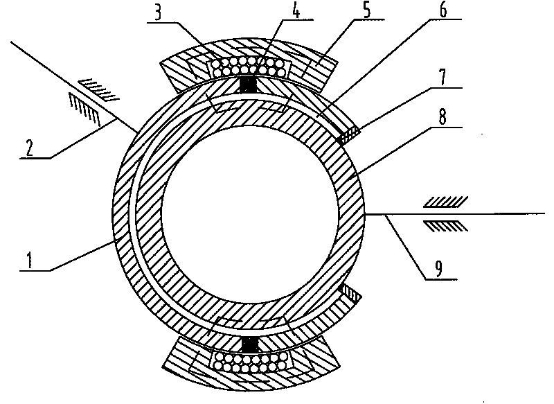
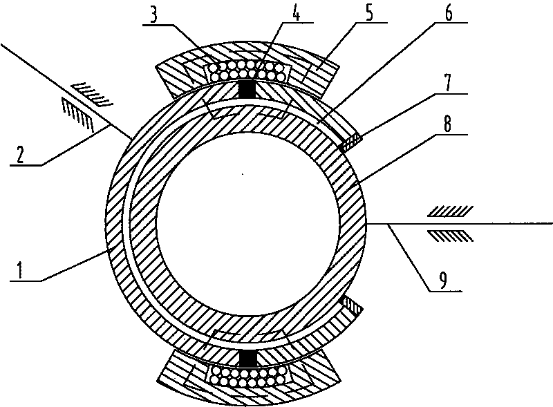
[0010] The spherical magneto-rheological fluid clutch of the present invention is mainly composed of a connected spherical steel sleeve 1, an input shaft 2, an excitation coil 3, a magnetic isolation ring 4, a sealing ring 7, a steel ball 8, and an output shaft 9, and the spherical steel sleeve 1 is fixed. On the input shaft 2, the steel ball 8 is fixed on the output shaft 9, and the steel ball 8 is arranged in the spherical steel sleeve 1. For reducing weight, the steel ball 8 is a hollow steel ball. The spherical steel sleeve 1 is embedded with a magnetic isolation ring 4, and the outside of the embedded magnetic isolation ring 4 is provided with a magnetic conduction ring 5 set on the spherical steel sleeve 1, and the magnetic conduction ring 5 corresponds to the magnetic isolation ring 4. There is an excitation coil 3, and the excitation coil 3 and the ...


PUM


Abstract

The invention relates to a spherical magnetorheological fluid clutch, comprising a spherical steel jacket fixed with an input shaft, a steel ball which is fixed with an output shaft and is arranged in the spherical steel jacket, and a magnetorheological fluid working gap filled with magnetorheological fluid is left between the spherical steel jacket and the steel ball, a round hole which leads the output shaft to pass through and is connected with the steel ball is arranged on the spherical steel jacket, a sealing ring is arranged at the periphery of the round hole, a magnetic separation ring is embedded on the spherical steel jacket, a magnetic-conduction ring sheathed on the spherical steel jacket is arranged outside of the embedded magnetic separation ring, and a magnet exciting coil is arranged in the magnetic-conduction ring, corresponding to the magnetic-conduction ring; a main round ball connected with the input shaft drives an output round ball to rotate by the magnetorheological fluid, the current magnitude in the magnet exciting coil is changed, that is, the transmission torque can be changed; the spherical magnetorheological fluid clutch can be used for the occasion that the included angle formed by the input shaft and the output shaft is not in a straight line and the occasion which has high requirements to spark; the structure is compact, the included angle of the input shaft and the output shaft can be changed and the clutch is suitable for small space; the equipment such as an electric brush does not need, and the safety reliability is high.

Description

technical field [0001] The invention relates to a clutch, in particular to a spherical magneto-rheological fluid clutch. Background technique [0002] Traditional mechanical clutches have defects such as impact, high noise, high inertia, severe friction and wear, and heat generation, short service life, and inconvenient control; traditional fluid-viscous clutches control the transmitted torque by adjusting the thickness of the oil film. It can effectively overcome the shortcomings of traditional mechanical clutches, but it requires a huge oil supply system and complex control devices, and the entire system is bulky and expensive. In recent years, magneto-rheological fluid technology has developed rapidly. Magneto-rheological fluid clutches can overcome the shortcomings of traditional mechanical and fluid-viscous clutches. By changing the magnitude of the current, you can easily control the magnitude of the torque transmitted by the equipment. The control is simple and conven...

Claims


Application Information

Patent Timeline
IPC IPC(8): F16D35/00
Inventor 侯友夫田祖织
Owner XUZHOU WUYANG TECH
Learn More