Supercharge Your Innovation With Domain-Expert AI Agents!

Micro-mechanical tuning fork gyroscope of horizontal shaft

A tuning fork gyroscope and micro-mechanical technology, applied in the direction of gyro effect for speed measurement, gyroscope/steering induction equipment, generator/motor, etc. It is difficult to solve the problems of performance degradation such as mechanical coupling of gyro driving mode and detection mode, variable area detection capacitance linearity, etc., and achieve the effect of large range, solving mechanical coupling problems and good performance.

Inactive Publication Date: 2010-06-02
PEKING UNIV
View PDF0 Cites 5 Cited by
  • Summary
  • Abstract
  • Description
  • Claims
  • Application Information

AI Technical Summary

Problems solved by technology

This makes it difficult to resolve the mechanical coupling between the gyro drive and detection modes
Therefore, most capacitive MEMS tuning fork gyroscopes, such as "A Micromechanical Comb Driven Tuning Fork Angular Rate Gyroscope" published by Bernstein et al. In the 21st International Conference on Micro-Electro-Mechanical Systems (MEMS'08), "A tuning-fork micro-gyroscope with a bias stability of 0.1° / hr" (J.Bernstein, S.Cho, et al. Micromachined Comb-Drive Tuning Fork Rate Gyroscope", in Proc. IEEE Micro Electro Mechanical Systems Workshop (MEMS'93), Fort Lauderdale, FL, Feb. 1993, pp. 143-148. and A. Sharma, M.F. Zaman, M. Zucher, F.Ayazi, "A 0.1° / hr bias driftelectronically matched tuning fork microgyroscope," in Proc.21th Int.Conf.Microelectromechanical Systems (MEMS'08), Tucson, USA, Jan.2008, pp.1-9), None of them solves the problem of mechanical coupling from the detection mode to the driving mode, so it is difficult to obtain high performance, especially high linearity
Moreover, the existing capacitive MEMS tuning fork gyro either adopts a variable-gap detection capacitor to obtain high sensitivity; or uses a variable-area detection capacitor to obtain high linearity and large range, which cannot solve the problem of high sensitivity and The contradiction of large range; the variable area detection capacitor is easily affected by the processing error, resulting in the reduction of linearity and other performance; the variable gap detection capacitor using differential detection is not sensitive to processing error

Method used


Image

  • Micro-mechanical tuning fork gyroscope of horizontal shaft
  • Micro-mechanical tuning fork gyroscope of horizontal shaft
  • Micro-mechanical tuning fork gyroscope of horizontal shaft

Examples


Embodiment Construction

[0019] The present invention will be described in detail below in conjunction with the accompanying drawings and embodiments.

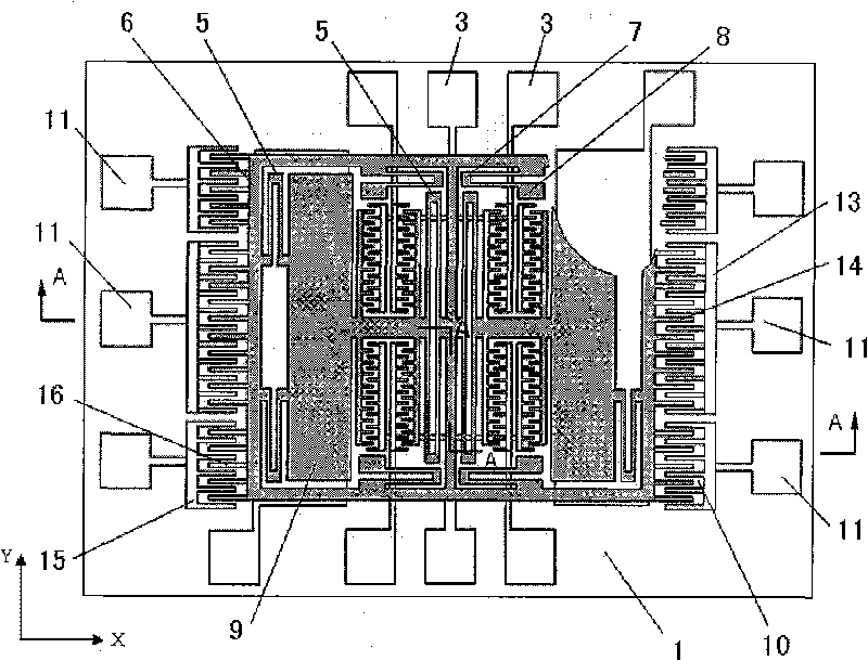
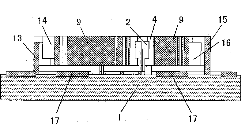
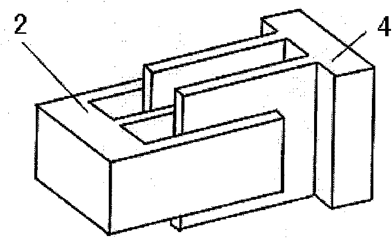
[0020] like figure 1 , figure 2 As shown, the present invention includes a substrate 1, a driving unit composed of a fixed driving comb 2, a driving electrode 3, a movable driving comb 4 and a driving folded beam 5, a frame 6, a detection folded beam 7, an anchor point 8 and a sensitive mass A sensitive unit composed of block 9 and a detection unit composed of two types of variable-area vertical comb-tooth detection capacitors 10 , corresponding detection electrodes 11 and differential detection variable-gap detection capacitors 12 . Among them, the variable-area vertical comb detection capacitor 10 includes a type I fixed vertical detection comb 13, a type I movable vertical detection comb 14, a type II fixed vertical detection comb 15 and a type II movable vertical detection comb 16; The capacitor 12 includes a detection plate 17 .

[0021] On t...


PUM


Abstract

The invention relates to a micro-mechanical tuning fork gyroscope of a horizontal shaft, which comprises a substrate, wherein a fixed driving comb and a driving electrode are in ohmic contact on the substrate and are both fixedly connected with the substrate; one side of a movable driving comb is connected with a frame by a driving folding beam, the frame is connected with and fixed at an anchor point on the substrate by a detection folding beam, and the other side of the frame is fixedly connected with a sensitive quality block; the sensitive quality block is fixedly connected with the frame by the driving folding beam, and the frame is fixedly connected on the substrate by the detection folding beam and the anchor point; and fixed vertical detection combs of I type and II type are fixed on the substrate, movable vertical detection combs of I type and II type are fixedly connected with the frame, and a detection electrode is in ohmic contact with the fixed vertical detection combs of I type and II type and is fixed on the substrate. Because of adopting a decoupling type driving capacitor, the invention solves mechanical coupling between a driving mode and a detection mode effectively. The invention can be widely applied to the detection of the rotating angular speed of objects in various fields.

Description

technical field [0001] The invention relates to a micro-mechanical gyroscope, in particular to a horizontal-axis micro-mechanical tuning fork gyroscope using a combined detection capacitor and a decoupling drive capacitor. Background technique [0002] In the past 20 years, micromechanical gyroscopes based on microelectromechanical systems (MEMS) technology have been extensively studied and developed rapidly. Capacitive MEMS vibrating gyroscopes are developing rapidly due to their simple structure and reliable operation. They have been used in consumer electronics, automobiles, medical rehabilitation, aerospace and even military fields. In order to obtain high-performance capacitive MEMS vibrating gyroscopes, researchers have to face technical difficulties such as device design, device processing, interface circuits and control loops. Among them, the device structure type and overall layout, drive unit and detection unit are the basic core issues in device design. Capaciti...

Claims


Application Information

Patent Timeline
IPC IPC(8): G01C19/56B81B7/02G01C19/5621
Inventor 郭中洋杨振川赵前程林龙涛刘雪松丁海涛崔健闫桂珍
Owner PEKING UNIV
Features
  • R&D
  • Intellectual Property
  • Life Sciences
  • Materials
  • Tech Scout
  • Unparalleled Data Quality
  • Higher Quality Content
  • 60% Fewer Hallucinations
Learn More