Reconfigurable mobile phone built-in antenna and implementation method thereof

A built-in antenna and antenna technology, applied in the direction of antenna, resonant antenna, electrical short antenna, etc., to achieve the best performance, large bandwidth, and low SAR value

Active Publication Date: 2010-06-02
HUAWEI DEVICE CO LTD
View PDF0 Cites 33 Cited by
  • Summary
  • Abstract
  • Description
  • Claims
  • Application Information

AI Technical Summary

Problems solved by technology

In the existing technology, it is difficult to obtain the best performance...

Method used


Image

  • Reconfigurable mobile phone built-in antenna and implementation method thereof
  • Reconfigurable mobile phone built-in antenna and implementation method thereof
  • Reconfigurable mobile phone built-in antenna and implementation method thereof

Examples


Embodiment Construction

[0019] In order to make the purpose, technical solutions and advantages of the embodiments of the present invention clearer, the technical solutions in the embodiments of the present invention will be clearly and completely described below in conjunction with the drawings in the embodiments of the present invention. Obviously, the described embodiments It is a part of embodiments of the present invention, but not all embodiments. Based on the embodiments of the present invention, all other embodiments obtained by persons of ordinary skill in the art without creative efforts fall within the protection scope of the present invention.

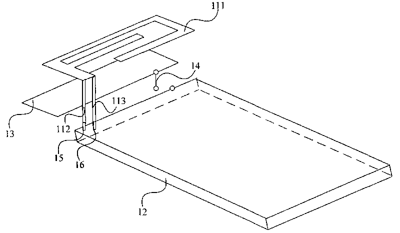
[0020] figure 1 It is a structural schematic diagram of the built-in antenna of the reconfigurable mobile phone according to the first embodiment of the present invention, including the main structure of the antenna, the ground area 12 printed on one side of the printed board, the additional ground area 13, the electronic switch 14 and the printed...


PUM


Abstract

The invention provides a reconfigurable mobile phone built-in antenna and an implementation method thereof. The reconfigurable mobile phone built-in antenna comprises an antenna main structure, an additional ground area, a ground area printed on one surface of a printed board, an electronic switch and an antenna feeding point and a grounding point printed on the other surface of the printed board, wherein the antenna main structure comprises a wiring structure of the antenna, a feeding spring piece which is in contact with the antenna feeding point and a grounding spring piece which is in contact with the grounding point, and the additional ground area is positioned under the wiring structure; the electronic switch is used for disconnecting the additional ground area with the ground area on one surface of the printed board when the antenna works at low-frequency frequency band and connecting the additional ground area with the ground area on one surface of the printed board when the antenna works at high-frequency frequency band. The reconfigurable mobile phone built-in antenna can lead the mobile phone antenna to acquire the optimal wireless performance in finite space.

Description

technical field [0001] Embodiments of the present invention relate to antenna technology, and in particular to a built-in antenna of a reconfigurable mobile phone and an implementation method thereof. Background technique [0002] The antenna performance of mobile phone antenna design faces two difficulties. One is how to obtain a larger bandwidth as much as possible when working in the low frequency band, and the other is how to control the specific absorption rate (Specific Absorption Rate, SAR) of electromagnetic radiation when working in the high frequency band. (Indicators to measure the intensity of electromagnetic radiation from mobile phones) increased. Commonly used mobile phone antennas generally have two solutions: Monopole antenna and PIFA antenna. The Monopole antenna has a wider bandwidth and higher SAR, while the PIFA antenna has a narrower bandwidth and lower SAR. In the prior art, it is difficult to obtain the best performance experience in a limited space ...

Claims


Application Information

Patent Timeline
IPC IPC(8): H01Q1/22H01Q21/30H01Q1/24H01Q1/50H01Q3/24H01Q3/44H01Q5/10H01Q9/42H01Q13/08H04B1/38H04B1/50H04M1/02
CPCH01Q9/0421H01Q1/245H01Q1/243H01Q1/48H01Q9/14H01Q5/0055H01Q5/364H01Q1/24H01Q9/04H01Q21/30
Inventor 班永灵帅培华雷平段恒毅
Owner HUAWEI DEVICE CO LTD
Why Eureka
Try Eureka