Switched reluctance motor for capacitance split circuit

A technology of switched reluctance motor and reluctance motor, applied in electrical components, electromechanical devices, magnetic circuit static parts, etc., can solve the problems of long freewheeling time, low system efficiency, hindering the operation of switched reluctance motor, etc. Improve efficiency and save energy

Inactive Publication Date: 2010-06-02
WOLONG ELECTRIC GRP CO LTD
View PDF0 Cites 3 Cited by
  • Summary
  • Abstract
  • Description
  • Claims
  • Application Information

AI Technical Summary

Problems solved by technology

After the two-phase AB is energized, switch to the BC two-phase energization, and the A phase still conducts natural freewheeling through the freewheeling tube D1. However, no back pressure is applied to the A-phase coil, and the freewheeling time is long. Moreover, during the start-up process The increasing process angle of phase A current is much larger than the decreasing area of ​​phase A current, so it is easy to freewheel to the negative torque area, such as figure 2 As shown, the negative torque zone is between the angle θ3 to θ4
When phase A is running in the negative torque region, it hinders the operation of the switched reluctance motor, so the efficiency of the entire system is relatively low

Method used


Image

  • Switched reluctance motor for capacitance split circuit
  • Switched reluctance motor for capacitance split circuit
  • Switched reluctance motor for capacitance split circuit

Examples


Embodiment Construction

[0019] The following are specific embodiments of the present invention and in conjunction with the accompanying drawings, the technical solutions of the present invention are further described, but the present invention is not limited to these embodiments.

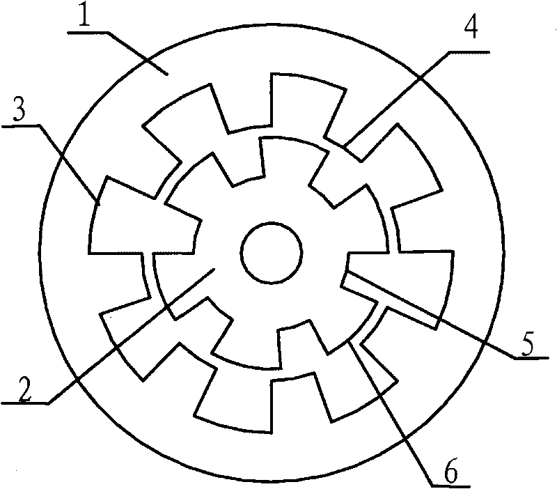
[0020] Such as image 3 As shown, the switched reluctance motor for capacitor splitting uses an 8 / 6 type four-phase switched reluctance motor, including a stator 1 and a rotor 2, and the outer ring surface of the stator 1 has stator grooves 3 and stator salient poles 4 that are evenly spaced. , the inner ring surface of the rotor 2 has rotor grooves 5 and rotor salient poles 6 that are evenly spaced. There are eight rotor salient poles 6 and six stator salient poles 4. For the convenience of description, the radian of the rotor 2 is defined as the rotor concave The sum of the 5 radians of the slot and the 6 radians of the salient pole of the rotor, and the radian of the stator 1 is defined as the sum of the 3 radians of th...


PUM


Abstract

The invention provides a switched reluctance motor for a capacitance split circuit, which belongs to the technical field of motors and solves the problem of low efficiency of the whole system because the operation of the traditional switched reluctance motor for a capacitance split circuit is hindered by long current endurance time of the phase A and the phase C of the switched reluctance motor. The switched reluctance motor for the capacitance split circuit comprises a stator and a rotor, wherein the external annular surface of the stator is provided with stator grooves and stator salient poles, which are uniformly distributed at intervals; the internal annular surface of the rotor is provided with rotor grooves and rotor salient poles, which are uniformly distributed at intervals; and the difference of the radian of the rotor grooves and the radian of the stator salient poles is less than the difference of the radian of the rotor salient poles and the radian of the stator grooves. The switched reluctance motor can reduce the natural current endurance time of the phase A and the phase C, improve the efficiency of the switched reluctance motor and save the energy resource.

Description

technical field [0001] The invention belongs to the technical field of motors, and relates to a switched reluctance motor, in particular to a capacitor split type switched reluctance motor. Background technique [0002] The switched reluctance motor has the advantages of simple structure, no motor winding on the rotor core, no permanent magnet, strong fault tolerance, high reliability, large starting torque, etc., and its application range is expanding day by day. The main circuit of the switched reluctance power converter includes an asymmetrical half-bridge conversion circuit, a double-winding power conversion circuit, a capacitor conversion circuit with storage, a regenerative conversion circuit, and a capacitor split conversion circuit. Among them, the capacitive split conversion circuit has the advantages of high winding utilization efficiency and fewer power devices, and thus is widely used. This patent takes the 8 / 6 type 4-phase switched reluctance motor as an exampl...

Claims


Application Information

Patent Timeline
Patent Type & Authority Applications(China)
IPC IPC(8): H02K29/00H02K1/14H02K1/24H02K1/16H02K1/26
Inventor 付贵霖
Owner WOLONG ELECTRIC GRP CO LTD
Why Eureka
Try Eureka