Mixed passive optical network system and transmission method thereof

A technology of passive optical network and transmission method, which is applied in the field of hybrid passive optical network system and its transmission, can solve the problems of high upgrade cost, impossibility, increase of the number of passive optical network access users, etc., and achieve low upgrade cost , the effect of smooth upgrade

Inactive Publication Date: 2010-06-02
SHANGHAI JIAO TONG UNIV +1
View PDF0 Cites 8 Cited by
  • Summary
  • Abstract
  • Description
  • Claims
  • Application Information

AI Technical Summary

Problems solved by technology

[0003] After searching the prior art documents, it was found that Ken-ichi Kitayama et al. published a paper entitled "OCDMA over WDM PON-solution to gigabit-symmetric FTTH (solve Gigabit uplink and downlink symmetry) in "Journal of Lightwave Technology (Journal of Lightwave Technology)". Fiber-to-the-home optical code division multiplexing/wavelength division multiplexing passive optical network)", this paper proposes a hybrid passive optical network structure of optical code division multiplexing/wavelength division multiplexing, in this structure The sending and receiving end of each group of signals in the system introduces an optical code division multiplexing encoder/decoder, thereby increasing the number of access users in the passive optical network, but this technology needs to be ineffective for the existing numerous wavelength division multiplexing. The optical line terminals and optical network units of the source optical network are redesigned and planned, and the upgrade cost is relatively high
[0004] After searching, it was found that Xu Wang et al published a paper entitled "field trial of 3-WDM*

Method used


Image

  • Mixed passive optical network system and transmission method thereof
  • Mixed passive optical network system and transmission method thereof

Examples


Embodiment Construction

[0024] The embodiments of the present invention are described in detail below in conjunction with the accompanying drawings: the present embodiment is implemented on the premise of the technical solution of the present invention, and detailed implementation methods and processes are provided, but the protection scope of the present invention is not limited to the following implementations example.

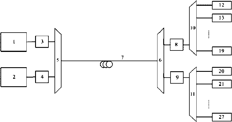
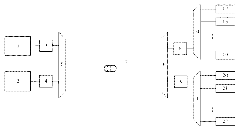
[0025] Such as figure 1 As shown, the hybrid passive optical network system involved in this embodiment includes: a first optical line terminal 1, a second optical line terminal 2, an optical code division multiplexing encoder / decoder 3 for the first terminal, and an optical code division multiplexer for the second terminal. Division multiplexing encoder / decoder 4, first node optical code division multiplexing encoder / decoder 8, second node optical code division multiplexing encoder / decoder 9, terminal optical multiplexing / demultiplexing device 5, node optical multiplexing / Demult...


PUM


Abstract

The invention discloses a mixed passive optical network system and a transmission method thereof in the technical field of fiber optical communication. The mixed passive optical network system comprises an optical circuit terminal, an optical code division multiplexing coder/decoder, an optical multiplexer/de-multiplexer, feeder line optical fiber, a remote node and optical network units, wherein the output port of the optical circuit terminal is connected with the corresponding optical code division multiplexing coder/decoder, and the output of the optical code division multiplexing coder/decoder and the output of another optical code division multiplexing coder/decoder together enter the feeder line optical fiber through the optical multiplexer/de-multiplexer for transmission; after being transmitted to another optical multiplexer/de-multiplexer, optical signals are transmitted into the input port of other optical multiplexer/de-multiplexer; and after coding/decoding, the optical signals enter the remote node to be transmitted to each corresponding optical network unit. In the invention, the optical circuit terminal and the optical network unit structure of the transitional passive optical network does not need changing, the optical code division multiplexing coder/decoder has transparent signal format for the transmitted signals, and transparent capacity expansion and smooth updating of the system can be realized.

Description

technical field [0001] The present invention relates to a system in the technical field of optical fiber communication and a transmission method thereof, in particular to a hybrid passive optical network system and a transmission method thereof. Background technique [0002] The passive optical network provides the connection between the optical line terminal and multiple optical network units, and shares the optical fiber medium between the optical line terminal and the remote node. While saving costs, it can provide high-bandwidth data transmission. Access network bandwidth requirements provide a powerful solution. However, whether it is a TDM PON or a WDM PON, its limited time slot resources and wavelength resources limit the number of ONUs in the PON, so hybrid PONs should be used It is born, which provides a possibility for the system expansion of the passive optical network. A passive optical network that uses both wavelength resources and time slot resources has bee...

Claims


Application Information

Patent Timeline
IPC IPC(8): H04B10/12H04Q11/00
Inventor 陈荷肖石林朱敏史杰
Owner SHANGHAI JIAO TONG UNIV
Why Eureka
Try Eureka