Bar conveying device

A conveying device and bar material technology, applied in the field of workpiece conveying device and bar material conveying device, can solve the problems of low feeding accuracy, worsening working environment, and insufficient clamping, and achieve accurate feeding size, high degree of automation, The effect of high work efficiency

Active Publication Date: 2010-06-09
震环机床集团有限公司
View PDF7 Cites 16 Cited by
  • Summary
  • Abstract
  • Description
  • Claims
  • Application Information

AI Technical Summary

Problems solved by technology

The bar is constrained by ferrules that are adapted to its outer diameter and installed on the beam at a certain interval, that is, the bar is contained in several ferrules. This type of automatic feeding device has the following disadvantages: 1. Due to the long bar and There are different degrees of bending. When the bar rotates, a large centrifugal force will be generated, which will be transmitted to the material rack through the restraining ring or the restraining tube, so that the material rack will vibrate strongly. At the same time, the vibration will be transmitted to the spindle of the machine tool through the bar itself. , which seriously affects the accuracy of the machine tool spindle and shortens the service life of the machine tool
2. Vibration will greatly shorten the service life of the tool and reduce the processing quality. In severe cases, the cutting process cannot be carried out
3. The noise generated by the vibration is large, which deteriorates the working environment
4. The feeding mechanism adopts steel ball type, the clamping is not firm enough, the feeding accuracy is not high, and it is difficult to realize the automation of feeding

Method used


Image

  • Bar conveying device
  • Bar conveying device
  • Bar conveying device

Examples


Embodiment Construction

[0027] The following are specific embodiments of the present invention and in conjunction with the accompanying drawings, the technical solutions of the present invention are further described, but the present invention is not limited to these embodiments.

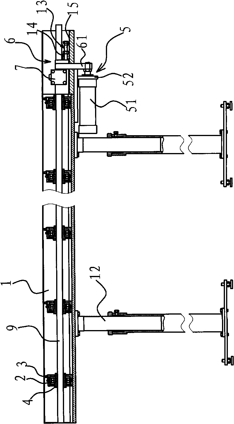
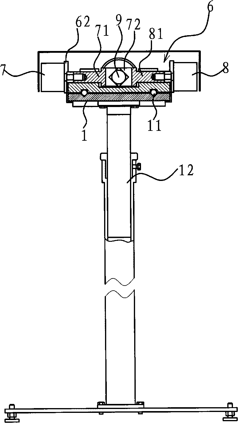
[0028] This bar material conveying device is used to transport the long bar material 9 that needs to be continuously processed at a fixed distance, and is installed on the feeding side of the CNC lathe, so that the CNC lathe can be continuously completed without re-clamping or stopping the machine tool. Processing of similar products.

[0029] Such as figure 1 with figure 2 As shown, the bar conveying device includes a frame 1, on which a guide mechanism for moving the bar 9 along one direction is provided, and on the frame 1 there is also a frame that can clamp the bar 9 The clamp 6, the clamp 6 is driven by a driving mechanism 5 to reciprocate linearly, and when the clamp 6 moves to the moving direction of the bar 9, ...


PUM


Abstract

The invention provides a bar conveying device, belongs to the technical field of machinery, and solves the problems that the conventional bar conveying device has large vibration and low feeding precision in the process of conveying. The bar conveying device comprises a machine frame, wherein the machine frame is provided with a guide mechanism used for enabling a bar to move along one direction;the machine frame is also provided with a fixture capable of clamping the bar; and the fixture does linear reciprocating motion under the drive of a driving mechanism, stays in a state of clamping the bar when moving towards the bar moving direction, and stays in a loose state when returning towards the opposite direction. The bar conveying device has the advantages of high feeding precision, high feeding efficiency, little vibration, less noise, long service life and the like.

Description

technical field [0001] The invention belongs to the technical field of mechanical processing, and relates to a workpiece conveying device, in particular to a bar material conveying device. Background technique [0002] Although the CNC lathe can automatically complete the machining of the part car at one time according to the set program. However, the automatic completion of the turning process is only from the beginning of the part processing to the completion of the turning process, and the feeding of the parts processed from the bar one by one still needs to be done manually. That is, every time a part is processed, it is necessary to open the door of the lathe, loosen the bar holder, manually shift the material, measure and adjust the length, lock the bar holder to clamp the bar, and close the door for the next same lathe processing. Every time a part is processed, the above-mentioned low-efficiency manual and complex operation process must be repeated, which makes the ...

Claims


Application Information

Patent Timeline
Patent Type & Authority Applications(China)
IPC IPC(8): B23B13/00B23B15/00
Inventor 金益红
Owner 震环机床集团有限公司
Why Eureka
Try Eureka