
Diagonally driven connecting rod pressure drive mechanism

A technology of transmission mechanism and connecting rod, which is applied in the field of pressure transmission and connecting rod pressure transmission mechanism, which can solve the problems of large lateral force of the slider and inconspicuous force increase effect, and achieve long working stroke, high positioning and repeat positioning accuracy , the effect of improving work efficiency

Inactive Publication Date: 2010-06-09
HUAZHONG UNIV OF SCI & TECH
View PDF0 Cites 10 Cited by
  • Summary
  • Abstract
  • Description
  • Claims
  • Application Information

AI Technical Summary

Problems solved by technology

[0003] The invention provides a connecting rod pressure transmission mechanism driven by an oblique pull, which solves the problem that the force increase effect of the existing press transmission mechanism is not obvious, and the lateral force of the slider of the crank connecting rod transmission and the toggle transmission mechanism is very large

Method used


Image

  • Diagonally driven connecting rod pressure drive mechanism
  • Diagonally driven connecting rod pressure drive mechanism
  • Diagonally driven connecting rod pressure drive mechanism

Examples


Embodiment 1

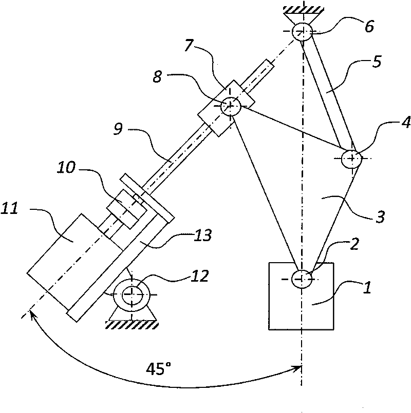
[0025] Embodiment one: if figure 1 As shown, this embodiment includes a servo motor 11, a connecting rod 5,

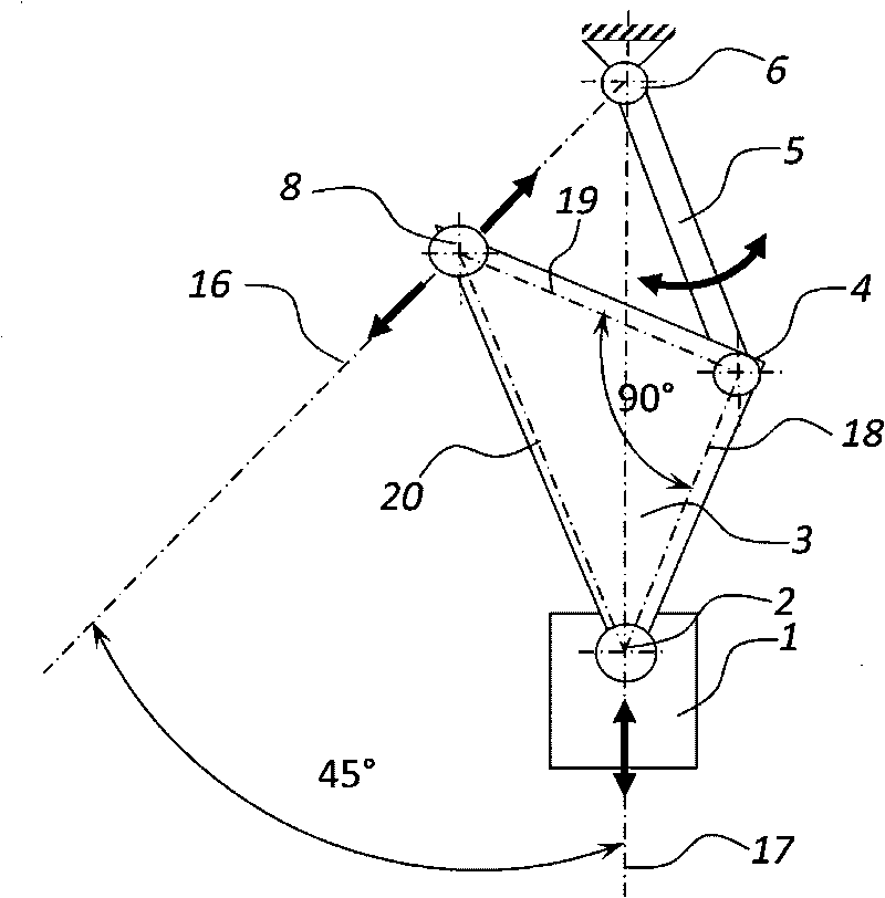
[0026] The connecting hinge 4, the driving hinge 8 and the slider hinge 2 are fixed on the triangular plate 3, and the connecting line of the axes of the three hinges forms an isosceles right triangle, and the axis of the connecting hinge 4 is located at the intersection of the two right angle sides of the isosceles right triangle, and the driving hinge 8 The shaft center and the slider hinge 2 shaft centers are respectively located at the intersection of the right-angled side and the hypotenuse;

[0027] One end of the connecting rod 5 is connected to the frame through the upper beam hinge 6, and the other end of the connecting rod 5 is connected to the triangular plate 3 through the connecting hinge 4. The distance between the axis center of the upper beam hinge 6 and the axis center of the connecting hinge 4 is the same as It is equal to the distance between the ax...

Embodiment 2

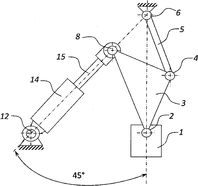
[0033] Embodiment two: if figure 2 As shown, in the present embodiment, the driving source is a hydraulic cylinder 14 driven by a hydraulic system, the end of the piston rod 15 of the hydraulic cylinder 14 is hinged with the drive hinge 8, and the bottom end of the hydraulic cylinder 14 is hinged with the fixed support hinge 12; The angle between the axis of the rod 15 and the vertical is 45 degrees. Driven by hydraulic pressure, the piston rod 15 can move forward and backward along the axis direction, thereby driving the driving hinge 8 hinged with the end of the piston rod 15 to move forward and backward along the axis direction.

[0034] The other components of this embodiment are the same as in Embodiment 1. The movement of the triangular plate 3, the connecting rod 5 and the slider is driven by the hydraulic cylinder 14, the piston rod 15 and the driving hinge 8, so that the slider can move along the vertical direction. Up and down movement.

[0035] The transmission p...


PUM

PropertyMeasurementUnit
Angleaaaaaaaaaa

Abstract

The invention relates to a diagonally driven connecting rod pressure drive mechanism, belongs to connecting rod drive mechanisms, and solves the problems of the traditional pressure drive mechanism that a force boosting effect is not obvious and a slide block side force cannot be eliminated. A connecting hinge, a driving hinge and a slide block hinge are fixed on a middle frame of the drive mechanism, wherein the connecting lines among the axle centres of the three hinges form an isosceles right triangle; two ends of the connecting rod are connected with a machine frame and the middle frame respectively through an upper cross beam hinge and the connecting hinge; a driving source is connected with the machine frame through a fixed support hinge; a main driving rod is connected with the middle frame through the driving hinge; and a slide block is connected with the middle frame through the slide block hinge. The diagonally driven connecting rod pressure drive mechanism of the invention has the characteristics of a hydraulic drive mechanism as well as the characteristics of crank connecting rod drive and toggle rod drive mechanisms, and has the force boosting effect; the mechanism can work with a rated load in most of the travel range of slide block movement, wherein the slide block has a very weak side force to a guide rail in the whole travel range of movement, can move at a changeable speed and can maintain pressure at a lower dead centre; and the mechanism is applied to the pressure drive of press machines or fixtures.

Description

technical field [0001] The invention belongs to a connecting rod transmission mechanism, in particular to an obliquely driven connecting rod pressure transmission mechanism, which is used for the pressure transmission of a press or a clamp. Background technique [0002] Crank-connecting-rod transmission press (see "Crank Press" / He Deyu / Mechanical Industry Press, 1987), toggle-drive press (see Optimum Design of Mechanical Press Toggle-Rod Transmission Mechanism, Zhang Yuantong, Zhu Denglin, Machinery and Electronics, 2008 (1), pp. 10-12), hydraulic transmission presses (see "Design and Application of Hydraulic Presses", author: Yu Xinlu edited and published by: Mechanical Industry Press) and screw transmission presses (see J58K series, CNC electric screw press, Wuhan Xinweiqi Technology Co., Ltd.) is currently the main equipment for plastic processing. However, there are some problems in the transmission mechanism and slider movement of these existing presses: 1. The slider ...

Claims


Application Information

Patent Timeline
IPC IPC(8): B30B1/10
CPCB30B1/103B30B1/16
Inventor 莫健华杨昊玥
Owner HUAZHONG UNIV OF SCI & TECH
Learn More