Rotary compressor
A compressor and rotary technology, applied in the direction of rotary piston machines, rotary piston pumps, mechanical equipment, etc., can solve the problems of piston burns, pressure differences, etc., and achieve the goal of improving burn resistance, suppressing performance reduction, and improving COP Effect
- Summary
- Abstract
- Description
- Claims
- Application Information
AI Technical Summary
Problems solved by technology
Method used
Image

Examples
no. 1 approach
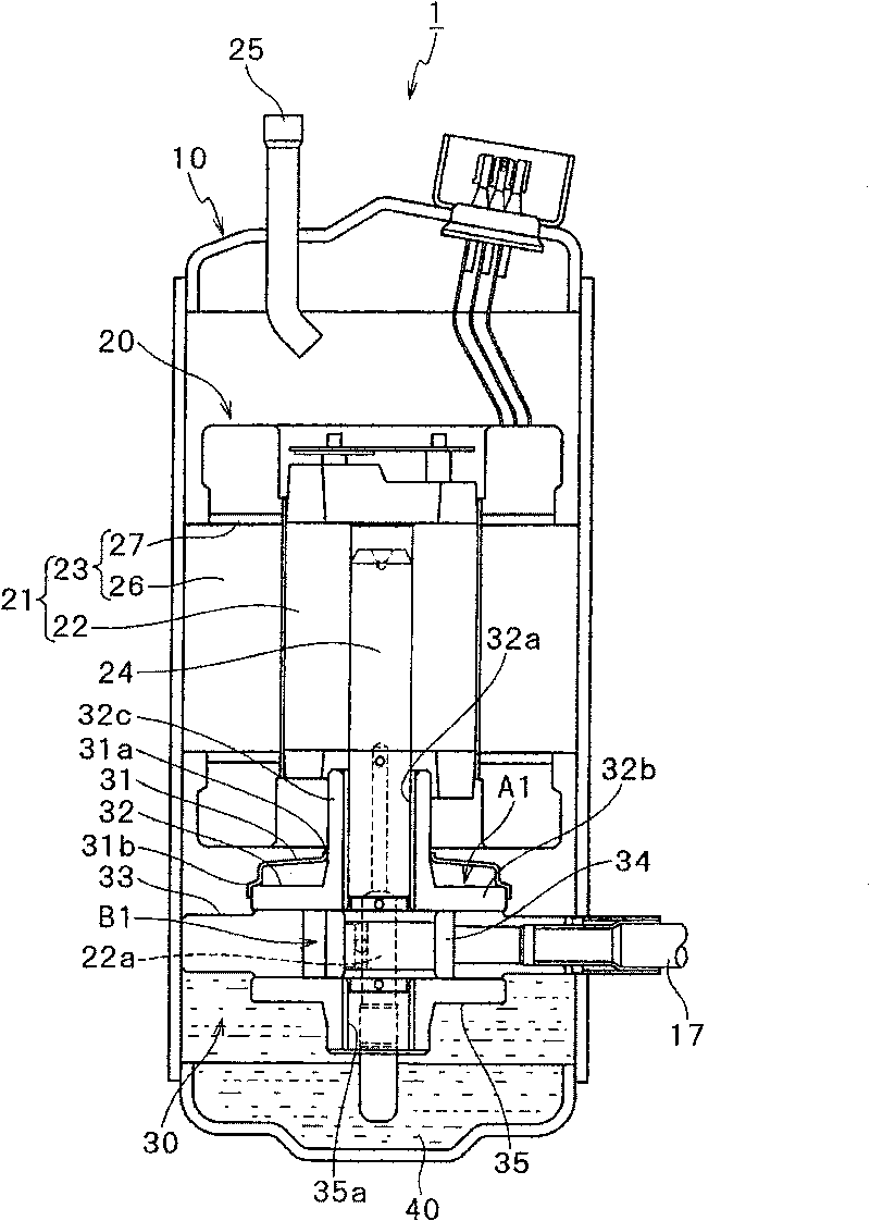
[0065] Hereinafter, a rotary compressor according to a first embodiment of the present invention will be described with reference to the drawings. figure 1 It is a schematic configuration diagram of the rotary compressor according to the first embodiment of the present invention.
[0066] The rotary compressor 1 compresses moisture-removed refrigerant gas introduced from an accumulator (not shown), and discharges the compressed refrigerant gas from a discharge channel 25 arranged at an upper end thereof. As refrigerant gas can be used e.g. CO 2 Refrigerant etc.
[0067] Such as figure 1 As shown, the rotary compressor 1 includes an airtight casing 10 , and a drive mechanism 20 and a compression mechanism 30 arranged inside the airtight casing 10 . The rotary compressor 1 is a so-called high-pressure dome-type compressor, and a compression mechanism 30 is disposed below the drive mechanism 20 in the airtight casing 10 . In addition, an oil reservoir 40 is arranged at the ...
no. 2 approach
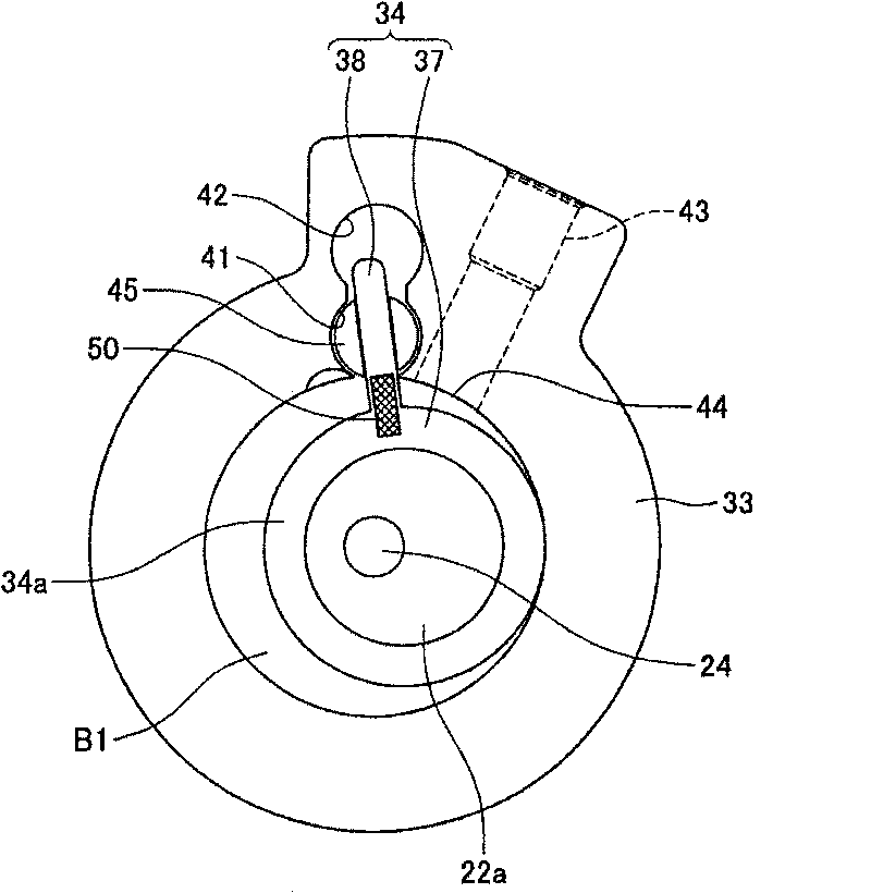
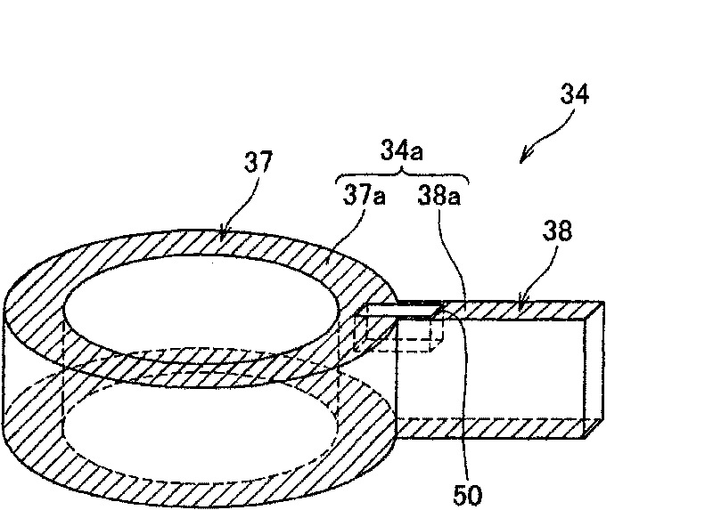
[0088] Next, refer to the following Figure 6 and Figure 7 A rotary compressor according to a second embodiment of the present invention will be described. Figure 6 It is a plan view explaining the structure inside the cylinder of the rotary compressor concerning 2nd Embodiment of this invention. Figure 7 yes Figure 6 Cross-sectional view of line B-B.
[0089] The second embodiment differs from the first embodiment in that the upper end of the oil supply hole is closed and the oil supply hole is connected to the oil reservoir. In addition, in 2nd Embodiment, since other structures are the same as 1st Embodiment, the same code|symbol as 1st Embodiment is attached|subjected and description is abbreviate|omitted.
[0090] Such as Figure 6 As shown, the cylinder 33 has a cylinder chamber B1 inside, and a holding hole 41 and an oil supply hole 142 provided outside the cylinder chamber B1. In this embodiment, the upper end of the oil supply hole 142 is as Figure 7 It is...
PUM
 Abstract
Description
Claims
Application Information
 - R&D
- Intellectual Property
- Life Sciences
- Materials
- Tech Scout
- Unparalleled Data Quality
- Higher Quality Content
- 60% Fewer Hallucinations
Browse by: Latest US Patents, China's latest patents, Technical Efficacy Thesaurus, Application Domain, Technology Topic, Popular Technical Reports.
© 2025 PatSnap. All rights reserved.Legal|Privacy policy|Modern Slavery Act Transparency Statement|Sitemap|About US| Contact US: help@patsnap.com