Middle-bent axial flow fan blade

An axial flow fan and blade technology, applied in the field of blade bending structure

Inactive Publication Date: 2010-06-09
GUANGDONG SUNWILL PRECISING PLASITC CO LTD
View PDF0 Cites 14 Cited by
  • Summary
  • Abstract
  • Description
  • Claims
  • Application Information

AI Technical Summary

Problems solved by technology

[0003] The purpose of the present invention is to provide an axial flow fan blade with a bent middle part of the blade, which can not only reduce the occurrence of vortices and turbulent flow caused by radial flow, improve th

Method used


Image

  • Middle-bent axial flow fan blade
  • Middle-bent axial flow fan blade
  • Middle-bent axial flow fan blade

Examples


Embodiment Construction

[0014] The present invention will be further described below in conjunction with the accompanying drawings.

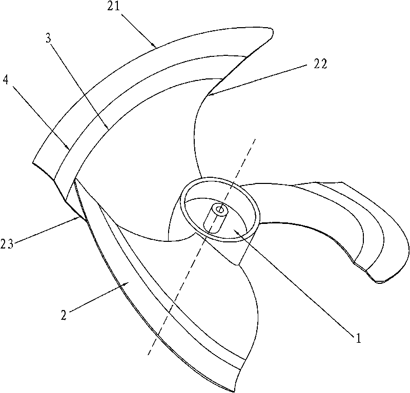
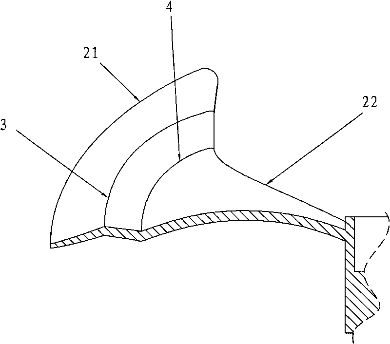
[0015] Such as figure 1 , figure 2 As shown, an axial flow fan blade with a bent middle part of the blade includes a hub 1 and a blade 2. The blade 2 includes an outer circumference 21, a leading edge 22 and a trailing edge 23. The blades 2 are arranged in the radial direction, A continuous crest 3, trough 4 undulation from the leading edge to the trailing edge.

[0016] The peaks 3 and troughs 4 are within the range from the vane located close to 80% of the outer circumference to the 95% of the outer circumference.

[0017] The bending width of the crest 3 or trough 4 is 10%D≤B≥5%D. D is the diameter of the wind wheel; B is the width of the bend.

[0018] The tops of the peaks 3 and the bottoms of the troughs 4 are obtuse angles.

[0019] The tops of the crests and the bottoms of the troughs may also have rounded corners.

[0020] Under the same conditions, to ...


PUM


Abstract

The invention discloses a middle-bent axial flow fan blade, which comprises a hub and a blade. The blade comprises an outer periphery, a front edge and a rear edge. The middle-bent axial flow fan blade is characterized in that: the blade is in a wave shape that at least one continuous wave crest and wave trough are arranged in the radial direction from the front edge to the rear edge. Due to the adoption of the structure, high pressure transferred to the outer periphery is dispersed and prevented. The middle-bent axial flow fan blade can reduce the vortex and turbulence caused by radial flow, thereby improving the air flowing environment, improving the static pressure and the efficiency, and reducing the noise. The middle-bent axial flow fan blade can solve the common deformation problem existing in fan blade molding in the mold production, thereby reducing the manufacturing cost.

Description

technical field [0001] The invention relates to a blade bending structure of a turbine air supply device, in particular to an axial flow fan blade for an air conditioner. Background technique [0002] At present, in the existing technology, most of the main bodies of the axial flow fan blades are connected by a continuous transition of a curve or a large arc. When this structure is rotating, the high pressure on the inner edge of the suction surface moves along the radial Transferred to the low pressure on the outer edge, this flow will cause disturbance on the suction side, resulting in the generation of vortices, thereby reducing the efficiency of the fan and increasing the noise. Since the outer edge and trailing edge of the blade have a certain influence on the generation and separation of the vortex; the middle part of the blade is equally important to the flow of the airflow and the generation of the vortex. Another important reason is that the deformation of the axia...

Claims


Application Information

Patent Timeline
IPC IPC(8): F04D29/38
Inventor 杨昕陈望明毛军祥温选锋
Owner GUANGDONG SUNWILL PRECISING PLASITC CO LTD
Why Eureka
Try Eureka