Ascending bed coal pyrolysis co-production circulating fluidized bed boiler combustion system and work method thereof

A circulating fluidized bed and boiler combustion technology, which is applied in the direction of fluidized bed combustion equipment, combustion methods, fuel burned in a molten state, etc., to ensure uniform mixing, improve the flow environment, and realize the effect of reaction depth and reaction process

Pending Publication Date: 2020-07-24
HUADIAN ELECTRIC POWER SCI INST CO LTD
View PDF2 Cites 0 Cited by
  • Summary
  • Abstract
  • Description
  • Claims
  • Application Information

AI Technical Summary

Problems solved by technology

[0006] The purpose of the present invention is to overcome the above-mentioned deficiencies in the prior art, and provide an ascending bed coal pyrolysis cogeneration circulating fluidized bed boiler combustion system with reasonable structure design and simple process flow to solve the problem of high efficiency of low-rank coal resources, Clean and comprehensive utilization can not only obtain high value-added pyrolysis oil and pyrolysis gas, but also greatly reduce the serious pollution, high-temperature corrosion and wear of the convective heating surface of the combustion furnace when the existing power plant boiler directly burns high-alkali coal It not only ensures the heat exchange effect of the heating surface, but also reduces the occurrence of tube burst accidents, improves the service life of the boiler, and prolongs the safe and stable operation period of the boiler.

Method used


Image

  • Ascending bed coal pyrolysis co-production circulating fluidized bed boiler combustion system and work method thereof

Examples


Embodiment Construction

[0024]The present invention will be further described in detail below in conjunction with the accompanying drawings and examples. The following examples are explanations of the present invention and the present invention is not limited to the following examples.

[0025] Example.

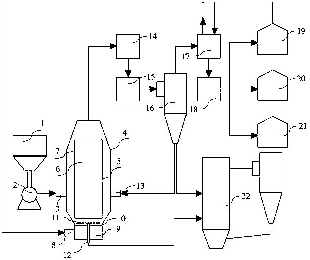
[0026] see figure 1 , in this embodiment, a combustion system for an ascending bed coal pyrolysis cogeneration circulating fluidized bed boiler, comprising a pulverized coal bin 1, a bin pump 2, an ascending bed pyrolysis furnace 4, a turbulent coalescer 14, and a high temperature centrifuge 15 , cyclone separator 16, pyrolysis oil gas cooling device 17, pyrolysis oil gas purification and separation device 18, pyrolysis gas collector 19, pyrolysis water collector 20, pyrolysis tar collector 21 and circulating fluidized bed boiler 22;

[0027] The ascending bed pyrolysis furnace 4 is equipped with a pulverized coal inlet 3, a heat carrier inlet 13, a guide tube 5, a guide area 6, an annulus area 7, ...


PUM


Abstract

The invention discloses an ascending bed coal pyrolysis co-production circulating fluidized bed boiler combustion system and a work method thereof. A coal powder bin, a bin pump, an ascending bed pyrolysis furnace, a turbulent flow coalescer, a high-temperature centrifuging device, a cyclone separator, a pyrolysis oil gas cooling device, a pyrolysis oil gas purifying and separating device, a pyrolysis gas collector, a pyrolysis water collector, a pyrolysis tar collector and a circulating fluidized bed boiler are included. The ascending bed pyrolysis furnace is provided with a coal powder inlet, a heat carrier inlet, a flow guiding barrel, a flow guiding area, an annular space area, an elevating air inlet, an air chamber, an air distribution plate and a bottom slag outlet. Pyrolysis producthigh-temperature semicoke in the ascending bed pyrolysis furnace is cyclically utilized and serves as a heat carrier, the heat of the semicoke is recycled, heat needed for coal powder pyrolysis is provided, meanwhile, the pyrolysis product high-temperature semicoke serves as raw materials of a combustion furnace, the situation that when high-alkali coal is directly combusted and used, the contentof alkali metal in the boiler exceeds the standard, consequently, the heated face of the boiler is stained, abraded and corroded is reduced, and the safety and the heat exchange effect of the heatedface are guaranteed.

Description

technical field [0001] The invention relates to the fields of coal chemical industry, energy and thermal power generation, in particular to an ascending bed coal pyrolysis cogeneration circulating fluidized bed boiler combustion system and a working method thereof. Background technique [0002] Coal is one of the conventional resources with the most abundant proven reserves in the world, of which low-rank coal accounts for a large proportion. Low-rank coal has many side chains in its chemical structure, high hydrogen and oxygen content, and has the characteristics of high moisture, low calorific value, good chemical reactivity, flammability and fragility, and is not suitable for long-distance transportation and storage. Existing low-rank coal processing and utilization technologies include direct combustion for power generation, direct liquefaction, gasification, and quality-enhancing processing. At present, low-rank coal is mainly used for pithead power generation, and a s...

Claims


Application Information

Patent Timeline
IPC IPC(8): F23C10/22C10B53/04
CPCF23C10/22C10B53/04F23C2206/10
Inventor 彭丽石战胜董方李宗慧柳冠青马治安
Owner HUADIAN ELECTRIC POWER SCI INST CO LTD
Why Eureka
Try Eureka