
Energy-saving stove

A stove and stove technology, which is applied in the field of combustion equipment, can solve the problems of deteriorating chef's working environment, uneven combustion firepower, and rising kitchen temperature, and achieve the effects of improving the working environment, reducing exhaust gas and heat emissions, and reducing the temperature of exhaust gas

Inactive Publication Date: 2010-06-09
FUZHOU RONGKUN KITCHEN EQUIP
View PDF0 Cites 4 Cited by
  • Summary
  • Abstract
  • Description
  • Claims
  • Application Information

AI Technical Summary

Problems solved by technology

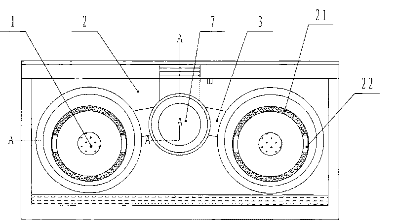
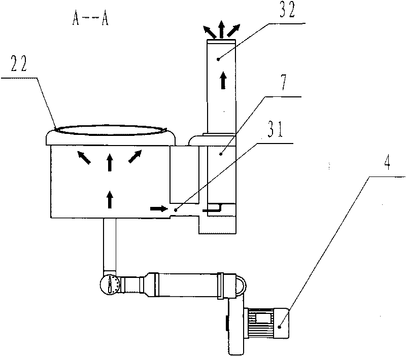
[0002] The stoves used in the catering industry have attracted widespread attention due to their long working hours, energy saving and high efficiency. figure 1 , figure 2 As shown, the flue gas is discharged by natural force, and there are air diffusers 22 on both sides of the pot seat ring 21 of the cooktop 2, affected by the traditional diesel stove and gas stove, there is a flue opening 31 leading to the smoke exhaust in the middle and lower part of the stove Road 3, a soup pot is arranged on the side of the smoke exhaust duct 3, and the heat of the flue gas is used to heat the water in the soup pot. Since the contact area between the flue exhaust duct 3 and the soup pot is small, the soup pot can only absorb a small amount of heat from the flue gas, and the temperature of the exhaust gas It still reaches 200-300 degrees, because there is only one flue opening 31 leading to the flue 3, resulting in uneven combustion firepower, and because of its lower position, unburned gas is easily discharged from it, resulting in waste
The air diffuser 22 guides the gas to rise, and at the same time emits a large amount of hot gas around the stove, which not only causes the heat loss of the gas, but also increases the temperature of the kitchen, and discharges exhaust gas to the kitchen, which deteriorates the working environment of the chef.

Method used


Image

  • Energy-saving stove
  • Energy-saving stove
  • Energy-saving stove

Examples


Embodiment 1

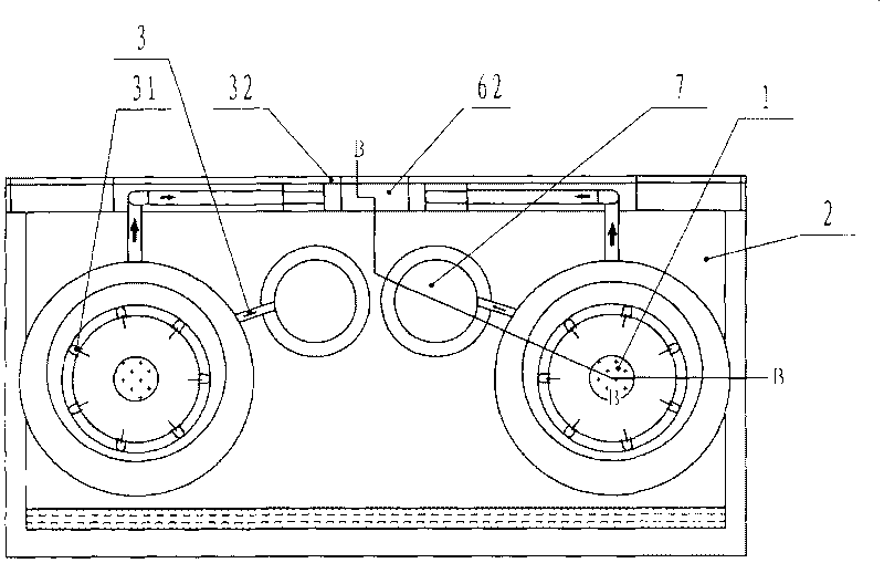
[0017] Example 1, such as image 3 , Figure 4 Shown, a kind of energy-saving cooker, it comprises furnace core 1, kitchen range top 2, exhaust flue 3, air blower 4, soup pot 7, also has an exhaust fan 5 to join with exhaust duct 3, the flue mouth 31 of exhaust duct 3 Located on the upper part of the stove, close to the bottom of the pot seat ring 21, the outside of the exhaust duct 3 is wrapped with the water tank 6, that is, the middle part of the exhaust duct 3 is immersed in the water tank 6, the exhaust duct 3 passes through the water tank 6, and its exhaust port 32 Can connect to outdoor, and water tank 6 communicates with soup pot 7, and the pot seat ring full circle on the kitchen range top 2 is a complete circumference, so that exhaust fan 5 sucks air. A plurality of smoke outlets 31 are evenly arranged on the circumference, and each smoke outlet 31 is connected to a coiled pipe exhaust duct 3, or multiple smoke exhaust outlets 31 are connected to a coiled pipe exhau...


PUM


Abstract

The invention belongs to combustion equipment, in particular to an energy-saving stove. The energy-saving stove of the invention comprises a stove core, a cooking bench, a discharge flue, a blast blower and a stockpot. The energy-saving stove is characterized in that: a floss hole in a hearth is positioned on the upper part of the hearth and is abutted against the lower part of a boiler seat ring; a water tank is wrapped outside the discharge flue and is communicated with the stockpot; an exhaust fan is connected with the discharge flue; and the whole boiler seat ring on the cooking bench is integrated circumference. The energy-saving stove has the advantages of changing conventional smoke venting, utilizing the blast blower to vent smoke in a centralized way, fully utilizing afterheat in flue gas, reducing the temperature of tail gas, fulfilling the aim of maximally saving energy in a way that steam can be connected out for use by a steamer or for sterilization and a cook can directly use hot water in a cooking process, and furthest reducing the discharge of the waste gas and heat of a boiler edge so as to improve the work environment of the cook, save energy and protect the environment.

Description

technical field [0001] The invention belongs to combustion equipment, in particular to an energy-saving stove. Background technique [0002] The stoves used in the catering industry have attracted widespread attention due to their long working hours, energy saving and high efficiency. figure 1 , figure 2 As shown, the flue gas is discharged by natural force, and there are air diffusers 22 on both sides of the pot seat ring 21 of the cooktop 2, affected by the traditional diesel stove and gas stove, there is a flue opening 31 leading to the smoke exhaust in the middle and lower part of the stove Road 3, a soup pot is arranged on the side of the smoke exhaust duct 3, and the heat of the flue gas is used to heat the water in the soup pot. Since the contact area between the flue exhaust duct 3 and the soup pot is small, the soup pot can only absorb a small amount of heat from the flue gas, and the temperature of the exhaust gas Still reach 200-300 degree, because only one flu...

Claims


Application Information

Patent Timeline
IPC IPC(8): F24B1/26F24B1/20F24B1/183F24B1/191
Inventor 林宝蓉
Owner FUZHOU RONGKUN KITCHEN EQUIP
Learn More