Co-graduation surface full-spectrum target

A full-spectrum, target technology, applied in spectrometry/spectrophotometry/monochromator, optical radiation measurement, measurement device, etc. problems, to reduce the influence of measurement accuracy, expand the test range, and simplify the structure of the instrument

Inactive Publication Date: 2010-06-09
BEIJING INSTITUTE OF TECHNOLOGYGY
View PDF0 Cites 21 Cited by
  • Summary
  • Abstract
  • Description
  • Claims
  • Application Information

AI Technical Summary

Problems solved by technology

The main defect of the alignment target is that the target surface is a whole piece of material, and its thermal diffusion will cause the spot to increase. When the repetition frequency laser pulse is used for marking, there will be a phenomenon that multiple light spots cannot be distinguished, which will affect the alignment. Benchmark Calculation Accuracy
When measuring the optical axis of laser, infrared and visible light systems, the control conversion must be adjusted manually or mechanically, which increases the offset error of system measurement
The reference cross reticle used in this measurement process is not consistent, and the laser, visible, and infrared reticle targets cannot be completely unified, and the absolute non-adjustment characteristics of the laser, visible, and infrared reticle targets cannot be realized.
[0007] The above-mentioned full-spectrum optical axis measurement methods all use laser, visible, and infrared optical axis separation detection and alignment. However, since the laser, visible, and infrared division targets cannot be completely unified, it is difficult to ensure the consistency between the targets. Therefore, there are deficiencies such as low measurement and calibration accuracy, low efficiency, and low degree of automation

Method used


Image

  • Co-graduation surface full-spectrum target
  • Co-graduation surface full-spectrum target
  • Co-graduation surface full-spectrum target

Examples


Embodiment 1

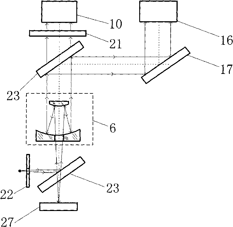
[0043] The structure of Embodiment 1 of the present invention is as follows Figure 8 As shown, the 0.5 μm-14 μm co-divided full-spectrum ZnS cross-divided target 25 includes: a ZnS substrate 8, a four-quadrant detector 22 and a star point hole 9, wherein the four-quadrant detector 22 is fabricated on the ZnS substrate 8, The star point hole 9 is located at the center of the ZnS substrate 8 .

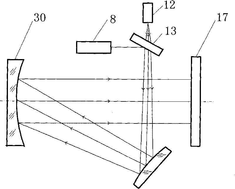
[0044] Measure the parallelism of visible light axis, infrared light axis, laser emitting axis and laser receiving axis: place the full-spectrum light source 1 at the focal point of the parabolic reflector 7, and the reflected parallel beam evenly irradiates the ZnS reticle target 25, ZnS reticle The reticle target 25 is placed at the focal point of the image space of the optical collimation system 6. After the parallel beam of the full-spectrum light source 1 is imaged by the ZnS cross reticle target 25 and the optical collimation system 6, a parallel beam is emitted, which is imaged b...

Embodiment 2

[0052] The structure of the second embodiment of the present invention is as Figure 9 As shown, the 0.5 μm ~ 14 μm co-divided full-spectrum ZnS cross-reticle target 26 includes: ZnS substrate 8, chromium thin film layer 33, four-quadrant detector 22 and star point hole 9, wherein the chromium thin film layer 33 is plated on the ZnS On the area outside the dividing line of the substrate 8, the four-quadrant detector 22 is fabricated on the chromium thin film layer 33, and the star point hole 9 is located at the center of the ZnS substrate 8.

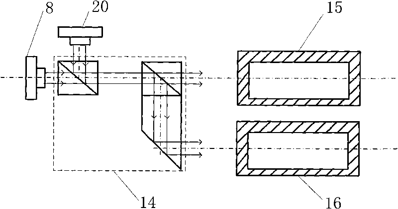
[0053] Measure the parallelism of visible light axis, infrared light axis, laser emitting axis and laser receiving axis: take the cross reticle 34 of the ZnS cross reticle target 26 as the alignment target, when the center of the imaging spot coincides with the center of the observation screen, it proves that the visible light system 16 is parallel to the optical axis of the infrared system 15 . A star point hole 9 is formed in the cent...


PUM


Abstract

The invention belongs to the technical field of photoelectronic imaging and testing and relates to a co-graduation surface full-spectrum target. The invention comprises a substrate, a multi-quadrant detector, an asterion hole and a graduation line, wherein the multi-quadrant detector is arranged in the region outside the graduation line of the substrate, the graduation line is the region dividing line of the multi-quadrant detector, the asterion hole is a through hole and arranged in the centre of the substrate, and the substrate is made of full-spectrum transmission materials, the gradation line is any graph with identification characteristics. The invention applies the materials capable of transmitting full-spectrum waveband to the substrate of a gradation plate, greatly reduces the influence of manual or mechanical regulation control conversion on measurement precision. The graduation plate is capable of realizing the integrated functions of visual, infrared and laser graduation targets, has the advantages of high precision, small volume and light weight, is free from imbalance, and can be applied to a full-spectrum multi-optical axis consistency detection system for realizing graduation collimation with high precision and without imbalance.

Description

technical field [0001] The invention relates to a co-division full-spectrum target technology, belongs to the technical field of photoelectric imaging and testing, and can be widely used in the measurement and calibration of photoelectric imaging systems. technical background [0002] Many photoelectric sighting and tracking systems are mainly used for all-weather reconnaissance, guidance, and tracking targets. They are usually composed of multiple optical axis systems such as visible light sighting, infrared thermal imaging, and laser ranging. The parallelism of the optical axes of each subsystem is an important factor. parameters. The multi-optical axis parallelism calibration system is a precision calibration device for testing and calibrating the multi-optical axis parallelism of the above-mentioned photoelectric sighting and tracking system. It consists of a collimating objective lens, a reticle, a light source and a signal acquisition and processing system and so on. ...

Claims


Application Information

Patent Timeline
Patent Type & Authority Applications(China)
IPC IPC(8): G01J3/02
Inventor 赵维谦贾馨徐荣甫沙定国邱丽荣
Owner BEIJING INSTITUTE OF TECHNOLOGYGY
Why Eureka
Try Eureka