
Abbe refractometer and light path realization method

A technology of incident surface and outgoing surface, which is applied in the field of Abbe refractometer and optical path realization, can solve the problems that restrict the accuracy of automatic Abbe refractometer, is not conducive to the miniaturization of the instrument, and the cost of the instrument is high, so as to achieve light weight and structure. Simple, low-cost effect

Active Publication Date: 2012-05-23
上海仪电物理光学仪器有限公司
View PDF0 Cites 0 Cited by
  • Summary
  • Abstract
  • Description
  • Claims
  • Application Information

AI Technical Summary

Problems solved by technology

[0012] 2. The condenser lens and prism are separated, which increases the volume of the instrument
[0013] 3. A large number of optical components lead to high instrument costs
[0014] 4. Using multiple LED light source groups to achieve large-scale measurement makes the system more complex, bulky, and expensive, which is not conducive to the miniaturization of the instrument
[0015] 5. The CCD array deviates from the rear focal plane of the lens, causing the transition from the dark area to the bright area to be too wide, that is, the change is not sharp, which affects the accuracy
[0016] 6. Since the existing automatic Abbe refractometers all use lens imaging, and the lens always has aberrations, which restricts the further improvement of the accuracy of the existing automatic Abbe refractometers

Method used


Image

  • Abbe refractometer and light path realization method
  • Abbe refractometer and light path realization method
  • Abbe refractometer and light path realization method

Examples


Embodiment Construction

[0033] The specific embodiments of the present invention will be further described below in conjunction with the accompanying drawings.

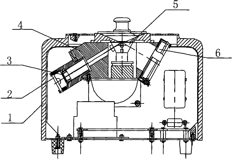
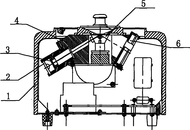
[0034] Such as figure 1 As shown, the optical path structure of the Abbe refractometer provided by the present invention includes an LED light source group 2, a linear array CCD receiving surface 6, and an optical path seat 4, and is characterized in that it also includes a condensing and refracting assembly 5, which has The sample measurement surface, the incident surface and the outgoing surface, the incident surface of the condensing and refracting component is perpendicular to the axis of the circular hole placed inside the optical path seat, and the axis of the circular hole is also perpendicular to the light-emitting surface of the LED light source group, The outgoing surface of the light-condensing component is parallel to the receiving surface of the linear array CCD, the incident surface of the light-condensing component is the inci...


PUM

PropertyMeasurementUnit
Apertureaaaaaaaaaa
Focal lengthaaaaaaaaaa
Clear apertureaaaaaaaaaa

Abstract

The invention relates to an Abbe refractometer, which comprises an LED light source group, a linear array CCD receiving surface and a light path seat, and is characterized by also comprising a condensing and refracting component, wherein the condensing and refracting component has a sample measuring surface, an incident surface and an exit surface; the incident surface of the condensing and refracting component is perpendicular to a hole axis in the light path seat which is perpendicular to the luminescentsurface of the LED light source group; the exit surface of the condensing and refractingcomponent is parallel to the linear array CCD receiving surface; the incident surface of the condensing and refracting component is an incident surface of a planoconvex condenser lens; and the exit surface of the condensing and refracting component is a waist surface of a prism. In the invention, the automatic Abbe refractometer has the advantages of light weight, small volume, easy production and assembly, low manufacturing cost, large measurement range and simple operation, and the precision of the Abbe refractometer is one magnitude order higher than the traditional Abbe refractometer.

Description

technical field [0001] The invention relates to the field of optical measuring instruments, in particular to an Abbe refractometer and an optical path realization method. Background technique [0002] Refractive index is one of the important physical constants of matter. Many pure substances have a certain refractive index. If there are impurities in them, the refractive index will change, and there will be deviations. The more impurities, the greater the deviation. Therefore, by measuring the refractive index, the purity of the substance can be determined. Abbe refractometer (also known as Abbe refractometer) is an instrument designed according to the principle of total reflection of light. It uses the method of measuring the critical angle of total reflection to measure the refractive index of unknown substances, and can quantitatively analyze certain components in the solution. It is one of the indispensable and commonly used equipment for factories, schools and research...

Claims


Application Information

Patent Timeline
IPC IPC(8): G01N21/43G01N21/01
Inventor 孙流星
Owner 上海仪电物理光学仪器有限公司
Learn More