Quick detachable joint of nuclear fuel assembly

A nuclear fuel assembly and fast technology, applied in the assembly of fuel elements, nuclear power generation, climate sustainability, etc., can solve the problem of unreliable disassembly and reassembly operations, fuel assemblies that cannot be used again, and sleeve screws that cannot be screwed in place, etc. problem, to achieve the effect of convenient removal and reinstallation of the upper pipe seat, saving man-hours, and accurate and reliable positioning

Active Publication Date: 2010-06-09
NUCLEAR POWER INSTITUTE OF CHINA
View PDF0 Cites 17 Cited by
  • Summary
  • Abstract
  • Description
  • Claims
  • Application Information

AI Technical Summary

Problems solved by technology

[0004] The upper tube seat cannot always be easily removed from the assembly, so a heavy auxiliary tool is required to provide enough external force to remove the upper tube seat; when disassembling, a loose part is produced, such as the AFA-3G assembly sleeve Screws, be careful not to drop this part during the disassembly and reassembly operation, resulting in more repair time, so the design without loose parts is more competitive; the disassembly and reassembly operation is not very reliable, Since the sleeve screw and the pipe seat of the AFA-3G component are made of stainless steel, the gap between the skirt and the pipe seat is very small, which may cause the sleeve screw to be seized during disassembly; and the sleeve screw may not be screwed in place during reassembly. , resulting in the fuel assembly being unusable

Method used


Image

  • Quick detachable joint of nuclear fuel assembly
  • Quick detachable joint of nuclear fuel assembly
  • Quick detachable joint of nuclear fuel assembly

Examples


Embodiment 1

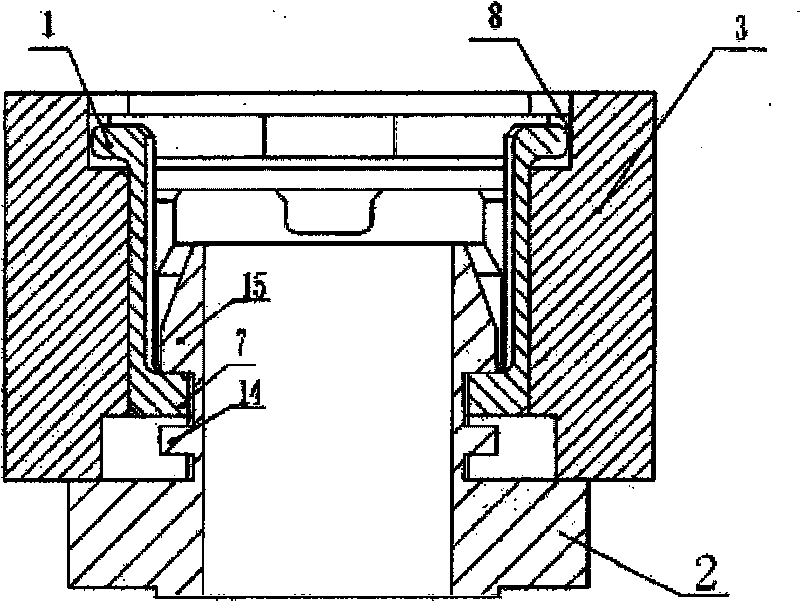
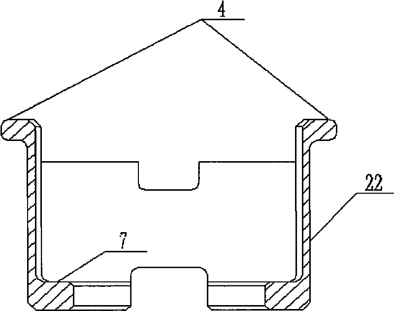
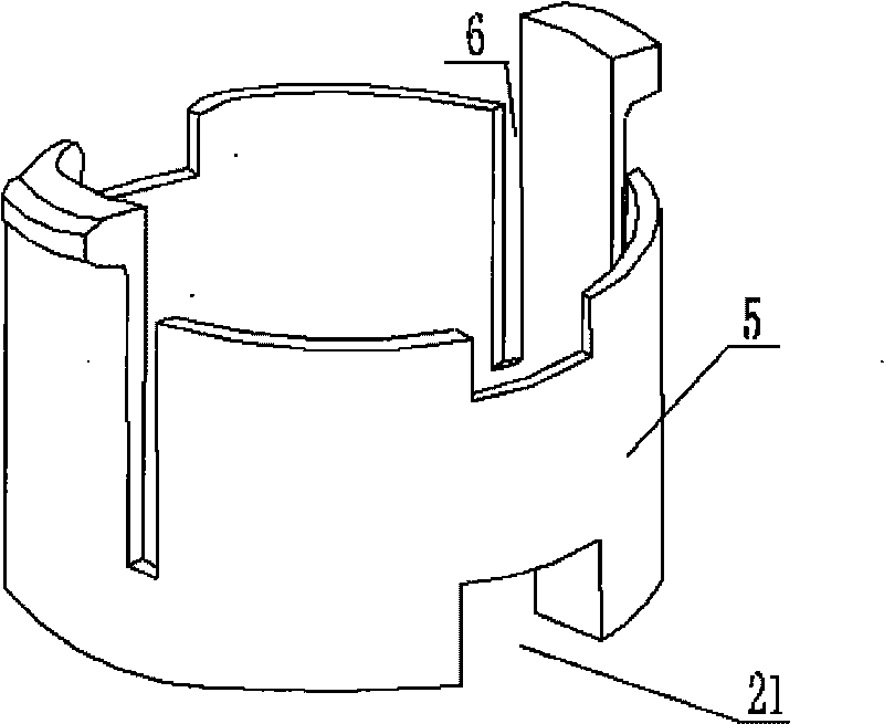
[0024] Such as figure 1 , figure 2 and image 3 As shown, a quick detachable joint of a nuclear fuel assembly is composed of a locking ring 1 , an upper stem 3 and a joint 2 . The locking ring 1 is a columnar hollow structure, and its lower end has an inwardly convex circular ring structure step 7 integrated with the lower end. There are two symmetrically distributed through grooves 21 at the step 7, and the upper end is connected vertically to the lower end. There are two symmetrically distributed tool grooves 6 in the direction of the groove line. The upper end of the locking ring 1 also has two symmetrically distributed straight arm positioning locking hooks 4 protruding radially along the locking ring 1. The locking ring 1. The position for fixing and positioning the locking claw 4 is a strip structure 22 whose radian is consistent with that of the side wall of the locking ring. An axial gap is provided between the upper part of the strip structure 22 and the side wall ...

Embodiment 2

[0027] Such as Figure 4 , Figure 5 As shown, a quick detachable joint of a nuclear fuel assembly is composed of a locking ring 1, an upper pipe seat 3 and a joint 2, wherein the upper pipe seat 3 and the joint 2 have the same structure as that described in Embodiment 1, and the locking ring 1 of this embodiment The upper end of the ring 1 has an arc structure. One end of the arc structure is a fixed end 16 fixed to the upper end of the locking ring or integrated with the upper end of the locking ring, and the other end is a free end 17. The arc structure and the side wall There is a gap along the circumferential opening of the locking ring. The curvature of the arc-shaped structure gradually decreases from the fixed end to the free end. It has an integrated structure with the free end 17, and the arc-shaped positioning and locking claw 18 is an arc-shaped structure. The locking ring installation groove 8 and the claw positioning pit 12 are matched with the convex part of th...


PUM


Abstract

The invention belongs to a component of a locking structure of a nuclear fuel assembly, particularly relates to a joint of an upper tube socket of a nuclear fuel assembly. The invention comprises an upper tube socket and a joint positioned in the upper tube socket, wherein a convex shoulder, a convex lug and a boss are arranged on the joint, a locking ring with a cylindrical hollow structure is also installed in the upper tube socket, the lower end of the locking ring is an inwards convex step, the upper end of the locking ring is provided with an outwards convex component which is matched with a mounting groove at the upper end of the upper tube socket, and the step of the locking ring is clamped in a groove formed between a convex tongue and the convex lug on the joint. Compared with the detachable upper tube socket of the domestic traditional nuclear fuel assembly, the structure is simple, the positioning is accurate and firm, a loose component can not be generated in the processes of disassembly and assembly, and the safety and the reliability are higher. The invention does not have spare parts, is convenient and quick for removing and reassembling the upper tube socket, saves the man-hour and has favorable maintainability.

Description

technical field [0001] The invention belongs to a locking structural component of a nuclear fuel assembly, in particular to a joint of an upper pipe seat of a nuclear fuel assembly. Background technique [0002] The locking structures of similar foreign products are composed of at least two parts, and the structure is relatively complicated. However, the sleeve screw detachable structure of the nuclear fuel assembly that is being used in China is due to the expansion of the sleeve screw and the upper tube seat of the fuel assembly. When removing the upper tube base, only destructive disassembly can be used. The sleeve screw cannot be reused, and loose There is a potential safety risk if the parts are removed. [0003] At present, the upper nozzle of AFA-3G fuel assembly adopts a detachable upper nozzle, which can repair the assembly in a reasonable time, and the damaged fuel rod can be replaced after the upper nozzle is removed. However, disassembly and reassembly operatio...

Claims


Application Information

Patent Timeline
Patent Type & Authority Applications(China)
IPC IPC(8): G21C3/30G21C3/33
CPCY02E30/40Y02E30/30
Inventor 黄新东雍泾黄辉徐林祥
Owner NUCLEAR POWER INSTITUTE OF CHINA
Why Eureka
Try Eureka