Permanent magnet generator rotor

A technology for permanent magnet generators and rotors, which is applied in the directions of magnetic circuit rotating parts, manufacturing stator/rotor body, magnetic circuit shape/style/structure, etc., which can solve the problems of reducing output power, sweeping chamber, and uneven magnetic density in the air gap and other issues to achieve the effect of weight reduction, uniform air gap and light weight

Inactive Publication Date: 2010-06-09
HENAN SENYUAN ELECTRIC CO LTD
View PDF1 Cites 4 Cited by
  • Summary
  • Abstract
  • Description
  • Claims
  • Application Information

AI Technical Summary

Problems solved by technology

Although the weight of this hollow permanent magnet generator rotor is greatly reduced, the air gap magnetic density is not uniform, and it is easy to "sweep the bore" or reduce the output power during operation.

Method used


Image

  • Permanent magnet generator rotor
  • Permanent magnet generator rotor
  • Permanent magnet generator rotor

Examples


Embodiment Construction

[0008] The present invention will be further described below in conjunction with accompanying drawing.

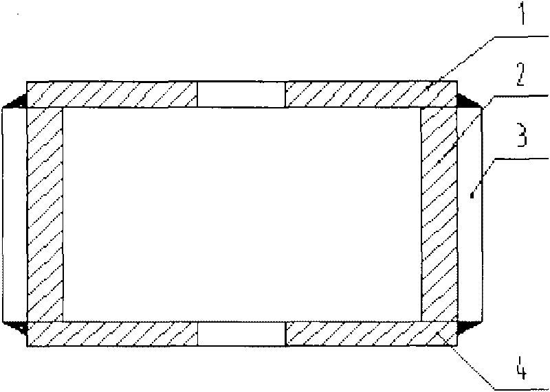
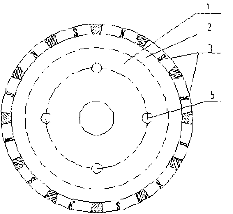
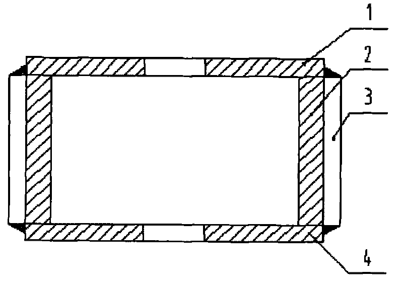
[0009] In the figure: 1. Upper pressing plate 2. Iron core 3. Permanent magnetic steel 4. Lower pressing plate 5. Bolts

[0010] As shown in the figure, the rotor of the permanent magnet generator of the present invention includes a rotating shaft, an iron core 2 and a permanent magnet steel 3. The iron core 2 is punched and laminated from circular silicon steel sheets, and the upper pressing plate 1 and the lower pressing plate 4 pass through 4 5 through-bolts are tightened, and the middle of the pressure plate is welded and fixed with the shaft. The outer circumference of the iron core 2 is evenly fixed with 16 permanent magnets 3 with alternating polarities. The shape of the permanent magnets 3 is a combination of trapezoid and rectangle. After positioning, epoxy resin is used to seal along the periphery of the permanent magnet steel 3 to form a cylindrical permanent mag...


PUM


Abstract

The invention discloses a permanent magnet generator rotor comprising a shaft, an iron core (2) and the permanent magnet steel (3). The iron core (2) is made by punching a ring-shaped silicon steel sheet and is stacked into the cylinder shape; the top surface and the bottom surface of the iron core (2) are pressed by pressing plates (1) and (4); the matched parts of the middle parts of the pressing plates (1) and (4) and a rotating shaft are welded and fixed together; a plurality of permanent magnet steel (3) whose poles are arranged alternatively are fixed on the outer circumference of the iron core (2) uniformly; the permanent magnet steel (3) is shaped like both a trapezoid and a rectangle; after the poles of the permanent magnet steel (3) are positioned, the periphery of the permanent magnet steel (3) is sealed with epoxy resin. The permanent magnet generator rotor is integrally in the shape of a cylinder, uses less permanent magnet steel, has good magnetic performance and high specific power and a lighter than the permanent magnet generator rotor having the same power, keeps uniform gap (air gap) with the inner cavity of a stator, can be easily and reliably processed and mounted, can output larger power than the permanent magnet generator rotor having the same weight and is suitable for the wind power generator which is mounted on a pole.

Description

technical field [0001] The invention relates to a permanent magnet generator rotor, in particular to a hollow permanent magnet generator rotor. Background technique [0002] Permanent magnet generator rotors are usually solid structures, such as interior permanent magnet (IPM), surface permanent magnet (SPM) and inlaid permanent magnet (ISPM). The weight of permanent magnet generators with solid rotors is large, and the specific power is relatively small. According to the definition of specific power (w / kg), in order to increase the specific power, the weight must be reduced. In recent years, permanent magnet generator rotors with hollow structures have appeared. Disclosed a kind of permanent magnet generator rotor as Chinese patent 96227429.1, there is a polygonal prism with a hole in the middle outside the rotating shaft, and bar-shaped permanent magnets are bonded on the outer cylindrical surface of the polygonal prism. Although the permanent magnet generator rotor wit...

Claims


Application Information

Patent Timeline
Patent Type & Authority Applications(China)
IPC IPC(8): H02K1/27H02K15/03
Inventor 邓隐北周保臣
Owner HENAN SENYUAN ELECTRIC CO LTD
Why Eureka
Try Eureka