
Resonance oscillation converter for improving synchronous rectification control

A resonant converter, synchronous controller technology, applied in output power conversion devices, control/regulation systems, high-efficiency power electronic conversion, etc., can solve the requirements of synchronous rectifier parasitic inductance, limited maximum operating frequency of 500kHz, low efficiency And other issues

Active Publication Date: 2010-06-09
SPI ELECTRONICS
View PDF0 Cites 5 Cited by
  • Summary
  • Abstract
  • Description
  • Claims
  • Application Information

AI Technical Summary

Problems solved by technology

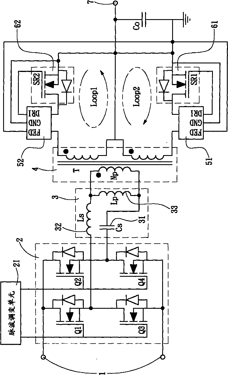
Although there are already integrated circuits on the market for controlling the synchronous rectifier switches 61, 62 (such as the product IR 1167 produced by the well-known company INTERNATIONAL RECTIFIER); however, the aforementioned IR 1167 is limited by the maximum operating frequency of 500 kHz, high cost and parasitic effects on the synchronous rectifier. Inductance has requirements, which limit the application of the above products in LLC synchronous rectification
[0003] At present, there is also a current driven synchronous rectifier (CDSR for short) that can meet the requirements of the above-mentioned LLC converter working at high frequency, but when the output current increases, it will produce two questions, one of which is figure 1 The synchronous controllers 51 and 52 of the two rectification circuits shown (such as Loop1 and Loop2 surrounded by dotted lines) will become too sensitive and prone to misoperation, and the AC impedance and the loop inductance formed by the rectification circuit will increase significantly and reduce efficiency. Because the current driven synchronous rectifier (CDSR) will become low efficiency, low energy density and negatively affect the performance of the LLC converter

Method used


Image

  • Resonance oscillation converter for improving synchronous rectification control
  • Resonance oscillation converter for improving synchronous rectification control
  • Resonance oscillation converter for improving synchronous rectification control

Examples


Embodiment Construction

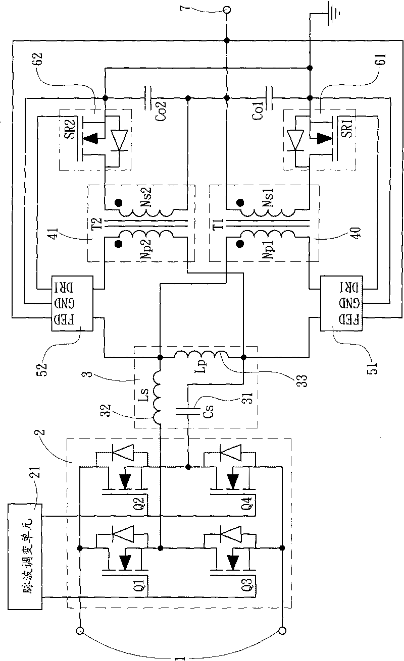
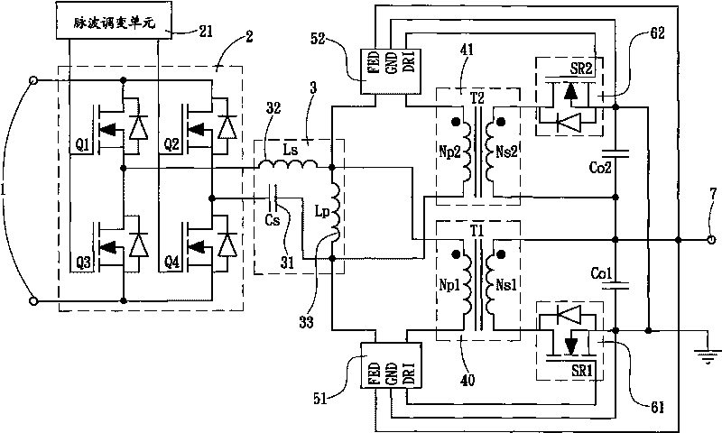
[0012] The present invention is a resonant converter with improved synchronous rectification control, and its circuit structure can be found in figure 2 , the resonant converter is connected to a power source 1 to obtain an input power, and the input power is direct current, and a pulse modulation unit 21 generates a driving pulse to control the on and off of a switching unit 2, thereby modulating The cycle and current flow direction of the input power sent to a resonant circuit 3, the resonant circuit 3 is composed of a resonant capacitor 31, a first resonant inductor 32 and a second resonant inductor 33 connected in series; in addition, the resonant circuit 3 The resonant converter is provided with two transformers 40, 41 electrically connected to the resonant circuit 3, and the primary side of the two transformers 40, 41 obtains the input power modulated by the resonant circuit 3, wherein the two transformers 40, 41 41 The side with the same polarity of the primary side wi...


PUM


Abstract

The invention relates to a resonance oscillation converter for improving synchronous rectification control. The resonance oscillation converter is connected with an electric power source for obtaining input electric power and controls the input electric power to be conveyed to a period of a resonant circuit; the resonance oscillation converter also comprises two transformers electrically connected with the resonant circuit, which are respectively and electrically connected with two synchronous controller units at the primary side of a dissimilar transformer and synchronous rectification switches respectively connected with the secondary sides of two similar transformers; the two transformers induce two induction electric power opposite in phase at the secondary side and the two synchronous controller units are connected with the transformer to induce voltage polarity change to provide a synchronized drive signal so as to respectively drive the synchronous rectification switches to conduct in an interactive way; as the synchronous rectification switches conduct in an interactive way, the induction electric power opposite in phase is rectified and conveyed to the output terminal. With the framework adopted, the structure of the transformer can be simplified, conversion efficiency can be improved and malfunction of the synchronous controller units can be avoided, thus making improvements in addressing high cost and low efficiency of existing circuits.

Description

technical field [0001] A resonant converter with improved synchronous rectification control, particularly a resonant converter utilizing an LLC resonant circuit. Background technique [0002] Due to the high efficiency of the LLC resonant circuit and its large input voltage and load range, it becomes a better conversion circuit architecture; however, if the LLC resonant circuit is used with a known technology diode rectifier circuit to provide output, the loss of the rectifier diode It will account for half of the overall loss, so to further improve efficiency, synchronous rectification technology must be used, and the LLC resonant converter provided by synchronous rectification technology can be seen in figure 1 , figure 1 It can be seen that the front end of the converter is connected to a power source 1 to obtain an input power, and the power source 1 is connected to a switching unit 2, and the switching unit 2 is controlled by a pulse modulation unit 21 to adjust the po...

Claims


Application Information

Patent Timeline
IPC IPC(8): H02M7/23H02M3/335
CPCY02B70/1475Y02B70/10
Inventor 徐明陈桥梁袁波
Owner SPI ELECTRONICS
Learn More