
Method, device and system for photolyzing, polarizing and multiplexing optical carrier

A polarization multiplexing and optical carrier technology, applied in the field of optical communication, can solve problems such as limited, very high requirements, and signal damage, and achieve the effects of improving tolerance, reducing device requirements and complexity, and improving spectrum utilization

Inactive Publication Date: 2010-06-09
HUAWEI TECH CO LTD
View PDF0 Cites 13 Cited by
  • Summary
  • Abstract
  • Description
  • Claims
  • Application Information

AI Technical Summary

Problems solved by technology

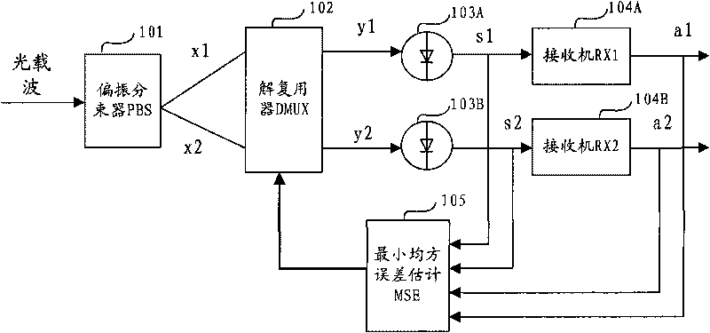
[0004] The existing technology uses polarization multiplexing of optical carrier to improve the spectrum utilization rate of the system, converts the polarization multiplexed modulation signal into an electrical signal and then demodulates it, and uses the mean square error of the demodulated signal as the feedback input signal to Controlling various parameters of the DMUX demultiplexer has very high requirements for analog-to-digital converters (ADC, Analog to Digital Convertor) and other devices; and since the single-carrier polarization multiplexing is divided into two transmission signals, the rate of each signal It will still be very high, even if the spectrum utilization can be improved to a certain extent through code pattern and filter adjustment, but this improvement is very limited, and it is easy to cause damage to the signal

Method used


Image

  • Method, device and system for photolyzing, polarizing and multiplexing optical carrier
  • Method, device and system for photolyzing, polarizing and multiplexing optical carrier
  • Method, device and system for photolyzing, polarizing and multiplexing optical carrier

Examples


Embodiment Construction

[0026] The technical solutions provided by the embodiments of the present invention will be further described in detail below in conjunction with the accompanying drawings. It should be noted that, for the convenience of description, the technical solution of the embodiment of the present invention is to separate the optical carrier into two optical sub-carriers for illustration. Those skilled in the art can fully understand that the separation of the optical carrier into two or more optical sub-carriers should be covered within the protection scope of the present invention.

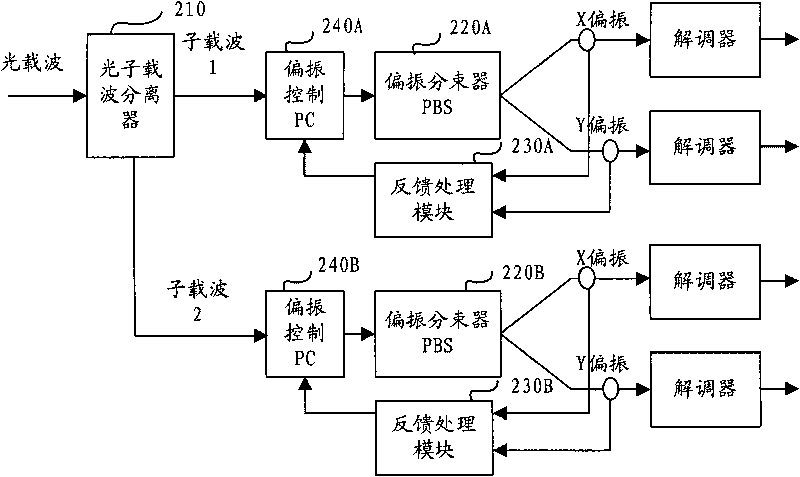
[0027] see figure 2 , figure 2 The device for optically depolarizing and multiplexing an optical carrier provided in an embodiment of the present invention includes:

[0028] An optical subcarrier separator 210, used to separate the optical carrier into two or more optical subcarriers at the receiving end;

[0029] Polarization beam splitters PBS (220A, 220B), used to optically depolarize and multip...


PUM


Abstract

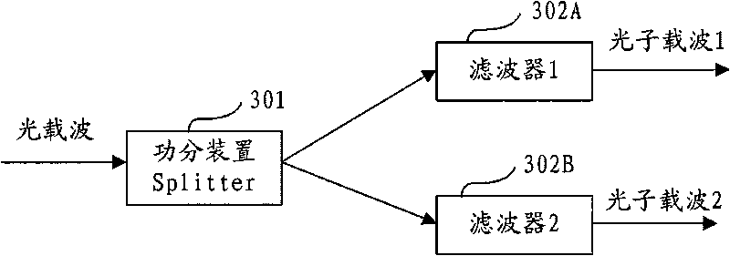
The embodiment of the invention discloses a method, a device and a system for photolyzing, polarizing and multiplexing an optical carrier, which relate to the technical field of optical communication, and can improve the frequency spectrum utilization ratio of the system, improve the tolerance limits of chromatic dispersion CD and polarization mode dispersion PMD, and simultaneously reduce the device requirement and the complexity of a receiving end. The method provided by the embodiment of the invention comprises the following steps of: separating the optical carrier into more than two paths of photon carriers at the receiving end; respectively photolyzing, polarizing and multiplexing each path of photon carrier into two paths of optical signals to be demodulated; and using the optical signals to be demodulated as feedback input signals, and respectively correspondingly regulating the incident angle of each path of photon carrier. Through the device photolyzing more than two paths of photon carriers and combining photolysis, polarization and multiplexing, the embodiment of the invention enables an optical carrier signal to be decomposed into more than four paths in an optical modulation format to be processed, and a DQPSK demodulator can be directly used on an optical wave for carrying out time delay interference detection to obtain an output signal.

Description

technical field [0001] The present invention relates to the technical field of optical communication, in particular to a method, device and system for optically depolarizing and multiplexing an optical carrier. Background technique [0002] With the development of optical communication technology, the single-channel rate is increasing day by day, and it has reached or exceeded 40Gbps at present. The increase in the rate will inevitably affect the spectrum utilization of the system, optoelectronic devices and the effects of Chromatic Dispersion (CD) and Polarization Mode Dispersion ( Polarization Mode Dispersion, PMD) tolerance has a higher requirement. [0003] see figure 1 , in the prior art, a polarization multiplexed modulated signal of an optical carrier is optically depolarized and multiplexed by a polarization beam splitter 101 (Polarization Beam Splitter, PBS) at the receiving end to obtain signals x1 and x2. Using the minimum mean square error estimation MSE algori...

Claims


Application Information

Patent Timeline
IPC IPC(8): H04B10/158H04B10/148H04J14/00H04B10/516H04B10/67
CPCH04B10/5165H04B10/671H04B10/676H04B2210/003H04J14/06
Inventor 熊前进李良川黄远达
Owner HUAWEI TECH CO LTD
Learn More