Implantable blood pump adopting driven suspension bearing

A suspension bearing and implantable technology, applied in suction devices and other directions, can solve the problems of complex mechanical structure, complicated control method and large volume of magnetic suspension blood pump, and achieve reduced energy input, less bearing wear and less heat generation. Effect

Inactive Publication Date: 2010-06-16
ZHEJIANG UNIV
View PDF2 Cites 18 Cited by
  • Summary
  • Abstract
  • Description
  • Claims
  • Application Information

AI Technical Summary

Problems solved by technology

[0003] Magnetically levitated blood pumps (see, for example, US Pat. No. 6,716,157B2 and US Pat. No. 6,264,635B1) have been successfully applied clinically, but the magnetically levitated blood pump requires complex mechanical structures, complex control methods, and consumes additional energy to maintain the suspension of the rotor. Therefore, large volume and high power consumption have become bottlenecks restricting the development of magnetically levitated blood pumps

Method used


Image

  • Implantable blood pump adopting driven suspension bearing
  • Implantable blood pump adopting driven suspension bearing
  • Implantable blood pump adopting driven suspension bearing

Examples


Embodiment Construction

[0026] The present invention will be further described below in conjunction with the accompanying drawings and embodiments.

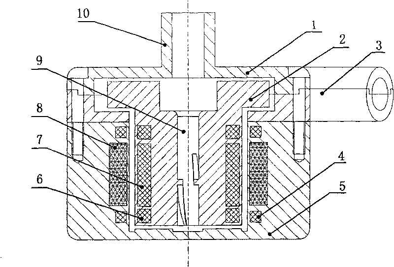
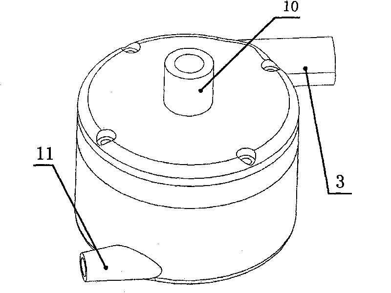
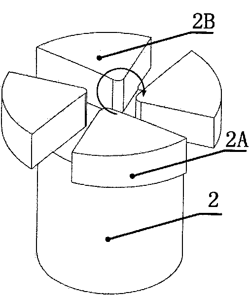
[0027] Such as figure 1 As shown, the present invention comprises pump upper case 1 and pump lower case 5, T-shaped rotor 2, suspension permanent magnet outer ring 4 and suspension permanent magnet inner ring 6, driving permanent magnet magnetic ring 7 and Drive the electromagnetic coil 8; insert the T-shaped rotor 2 with a drainage groove in the inner hole between the pump upper shell 1 and the pump lower shell 5, and the big end of the T-shaped rotor 2 is 4, 6 or 8 blades with an angle The impeller is composed of a driving electromagnetic coil 8 embedded around the inner wall of the pump lower casing 5, a floating permanent magnet outer ring 4 is embedded symmetrically up and down on the driving electromagnetic coil 8 of the inner wall of the pump lower casing 5, and a driving permanent magnet is embedded around the outer ring of the T-shaped rotor 2....


PUM


Abstract

The invention discloses an implantable blood pump adopting a driven suspension bearing. A T-shaped rotor with a drainage groove arranged in the inner hole is implanted between an upper pump casing and a lower pump casing; the large end of the rotor is an impeller consisting of 4, 6 or 8 blades with dip angles; driving magnet coils are implanted in the periphery of the inner wall of the lower pump casing; suspension permanent magnet outer rings are implanted in longitudinal symmetry in the driving magnet coils on the inner wall of the lower pump casing; driving permanent magnet rings are implanted in the periphery of the outer ring of the rotor; suspension permanent magnet inner rings are implanted in longitudinal symmetry in the driving permanent magnet rings on the outer ring of the rotor; the suspension permanent magnet outer rings and the driving magnet coils on the lower pump casing correspond to the suspension permanent magnet inner rings and the driving permanent magnet rings on the rotor; the outlet of the pump is arranged in the connection position between the upper pump casing and the upper part of the lower pump casing; and the bottom surface of the lower pump casing, corresponding to the small end of the rotor, is in a structure comprising 4, 6 or 8 bulges with dip angles. The pump has the advantages of less wear, less consumption, high shock resistance, reduced energy input of the blood pump, and reduced additional weight of the blood pump, therefore the blood pump is convenient to be developed to the light and portable type direction.

Description

technical field [0001] The invention relates to a medical device, in particular to an implantable blood pump adopting a passive suspension bearing. Background technique [0002] Mechanical blood pumps are recognized worldwide as effective devices for the treatment of advanced myocardial failure. Since Dr. John Gibbon successfully applied the artificial heart-lung machine he developed to clinical development in 1953, there are many blood pump manufacturing companies in the world. To the continuous flow rotation against the laws of nature. The rotary blood pump has roughly experienced three generations of technological innovation from being proven to be used as a heart assist to becoming the mainstream development direction of the artificial heart: the first generation was from 1965 to 1990, mainly mechanical shaft-sealed blood pumps, and in vitro Aiming at assisting circulation, representative devices include Biopump BP-80, Hemopump, Kyocera Gyro, etc.; the second generatio...

Claims


Application Information

Patent Timeline
Patent Type & Authority Applications(China)
IPC IPC(8): A61M1/12
Inventor 邹俊韩青阮晓东林哲杨华勇
Owner ZHEJIANG UNIV
Why Eureka
Try Eureka