Reversely bevelled flip bucket

A kind of oblique cutting and reverse technology, which is used in water conservancy projects, embankments, marine engineering and other directions, can solve the problems of oblique cutting and sills that cannot adapt to changes in discharge conditions, endangering the safety of the other side, and impacting river banks, etc., to reduce impact and scour. Destructive effect, weakening effect of scour

Inactive Publication Date: 2010-06-16
SICHUAN UNIV
View PDF0 Cites 6 Cited by
  • Summary
  • Abstract
  • Description
  • Claims
  • Application Information

AI Technical Summary

Problems solved by technology

However, since the water flow enters the river channel from the side, the direction of the water flow must have a certain angle with the channel. After the water flow enters the downstream channel, on the one hand, it moves towards the bottom of the river bed, forming scour pits at the bottom of the river bed; Move forward in the direction of entering the water. When the river channel is relatively narrow and the water flow velocity at the exit of the ridge is relatively high, the water flow will hit the opposite bank at a high velocity, and cause large waves on the opposite bank, endangering the safety of the opposite bank.
[0004] At present, with the vigorous development of my country's hydropower industry, the height difference between the upstream and downstream of the flood discharge structure is continuously increasing, and the water flow velocity at the exit of the bridge is also increasing. For example, the flow velocity at the exit of the flood discharge tunnel of Jinping I Hydropower Station exceeds 50m / s , so that the oblique cutting can no longer adapt to the energy dissipation of the change of drainage conditions.

Method used


Image

  • Reversely bevelled flip bucket
  • Reversely bevelled flip bucket
  • Reversely bevelled flip bucket

Examples


Embodiment 1

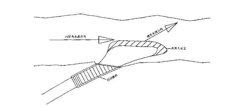
[0021] like figure 2 As shown, the reverse oblique cutting ridge provided in this embodiment is composed of a bottom plate 1 and side walls 2 erected along both sides of the bottom plate. The length of the wall 2 and the base plate 1, the edge of the base plate 1 between the ends of the two side walls 2 forms a hypotenuse, and the side wall 2 is a straight line, and the base plate 1 is a curved surface of equal width and curvature.

Embodiment 2

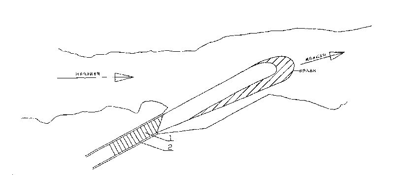
[0023] like image 3 As shown, the reverse oblique cutting ridge provided in this embodiment is also composed of the bottom plate 1 and the side walls 2 erected along both sides of the bottom plate. The length of the side wall 2 and the bottom plate 1 is that the edge of the bottom plate 1 between the ends of the two side walls forms a hypotenuse, and the bottom plate 1 is a curved surface of equal width and equal curvature, but the difference from Embodiment 1 is that the side wall 2 is curve, see Figure 4 .

Embodiment 3

[0025] like Figure 4 As shown, the reverse oblique cutting ridge provided in this embodiment is also composed of the bottom plate 1 and the side walls 2 erected along both sides of the bottom plate. The length of the side wall 2 and the bottom plate 1, the edge of the bottom plate 1 between the ends of the two side walls 2 forms a hypotenuse, and the side wall 2 is a curve, but the difference from embodiment 2 is that the bottom plate 1 is twisted with unequal width To meet with Figure 5 .


PUM


Abstract

The invention discloses a reversely bevelled flip bucket, which consists of a bottom plate and side walls erecting along two sides of the bottom plate and is characterized in that: length of one side wall and the bottom plate on one side of a mountain massif is shorter than that of the side wall and the bottom plate on the side close to a river so that the edge of the bottom plate positioned between two side wall end heads forms a bevel edge. The side walls of the bevelled flip bucket can be straight lines or curves; the bottom plate can be a curved surface or a warped surface with constant curvature; and the bottom plate can also be equal or unequal in width. The reversely bevelled flip bucket provided by the invention can diminish an included angle between water flow and the opposite bank under the action of the side wall close to one side of the river so as to weaken the impact the water flow on the opposite bank of the river, can increase the distance from the underwater water flow close to one side of the mountain massif to the opposite bank so as to increase energy consumption, and enables the water flow close to one side of the river to directly flow to the river bottom and form a water wall in the centre of the river, wherein the water wall prevents another part of the water flow flowing to the opposite bank so that flushing of the water flow to the opposite bank of the river can be weakened and the safety of a levee of the opposite bank is guaranteed.

Description

technical field [0001] The invention belongs to the technical field of energy-dissipating ridges built downstream of drainage structures in water conservancy projects, and in particular relates to a reverse obliquely cut ridge. Background technique [0002] The deflecting flow energy dissipation is to build a ridge downstream of the discharge structure, so as to use the huge kinetic energy of the discharge flow, that is, the flow velocity, to lift the water into the air, and then land on the downstream far away from the building. Since the water loses the constraint of the solid boundary (side wall and bottom plate) after flowing out of the ridge, a small part of kinetic energy is lost under the action of turbulence and air resistance, and most of the energy is lost when the water tongue enters the downstream water body, and the downstream Water bodies collide and mix with each other, coupled with the viscosity of water, under the action of strong shear and strong turbulence...

Claims


Application Information

Patent Timeline
Patent Type & Authority Applications(China)
IPC IPC(8): E02B3/10E02B8/06
Inventor 邓军刘善均许唯临王韦曲景学张建民田忠张法星
Owner SICHUAN UNIV
Why Eureka
Try Eureka