Al technical title is built by PatSnap Al team. It summarizes the technical point description of the patent document.
A vortex device and vortex wheel technology, applied in the field of vortex devices, can solve the problems of high energy consumption and low efficiency, and achieve the effect of wide pressure range
Inactive Publication Date: 2010-06-16
陈久斌
View PDF0 Cites 4 Cited by
Summary
Abstract
Description
Claims
Application Information
AI Technical Summary
This helps you quickly interpret patents by identifying the three key elements:
Problems solved by technology
Method used
Benefits of technology
Problems solved by technology
[0005] The existing suction equipment and vacuum equipment have defects such as high energy consumption and low efficiency
Method used
Image
Click on the blue label to locate the original text in one second.
Reading with bidirectional positioning of images and text.
Examples
Embodiment Construction
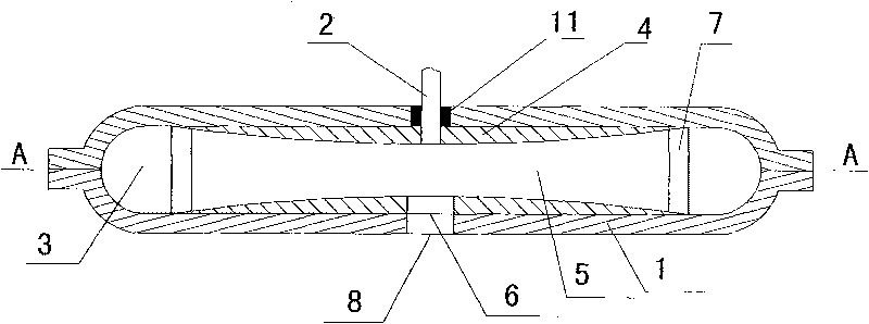
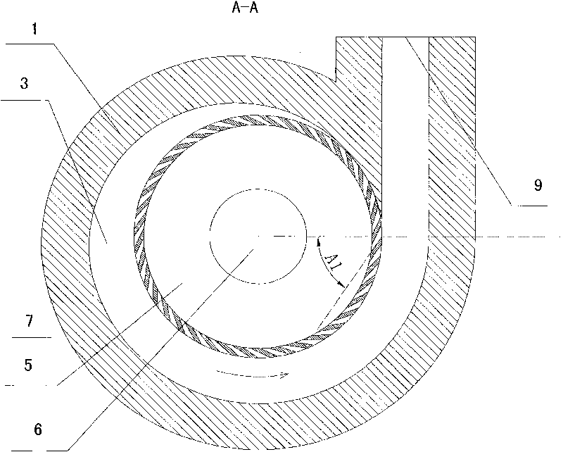
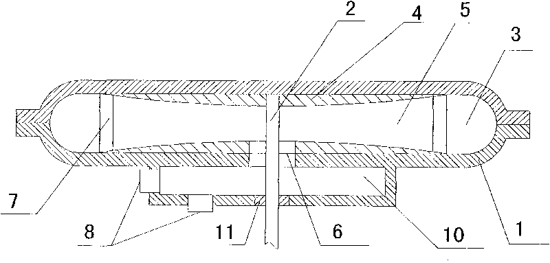
[0040] The main structure of the vortex generator of the present invention includes a housing 1 and a transmission shaft 2, which is characterized in that a transmission shaft 2 is installed in the housing 1, at least one vortex wheel 4 is arranged in the housing 1, the transmission shaft 2 is connected with the vortex wheel 4, and the vortex The wheel 4 is provided with a vortex chamber 5 , the middle part of the vortex chamber 5 is provided with a vortex chamber inlet 6 , a plurality of guide vanes 7 are arranged on the periphery of the vortex chamber 5 , and the housing 1 is provided with an inlet 8 .
[0041] The scope of the casing 1 includes a machine base, a casing, a protective cover, and a power unit, and each part can be collectively referred to as a casing. The housing can also be integrated with the power device to form an integral housing.
[0042] The power transmission shaft 2 can be set as a solid shaft or a hollow shaft, and the hollow shaft can be used as a f...
PUM
Abstract
The invention provides a swirler. The swirler comprises a shell and a transmission shaft, wherein the transmission shaft is arranged in the shell; at least one swirling wheel is arranged in the shell; the transmission shaft is connected with the swirling wheel; a swirling chamber is arranged in the swirling wheel; the middle part of the swirling chamber is provided with a swirling chamber inlet; the periphery of the swirling chamber is provided with a plurality of guide vanes; and the shell is provided with an inlet. The swirler makes full use of circumferential motion and fluid motion, causes fluid to be automatically sucked into eddy current from an eddy current central region by using the eddy current of which a rotational speed is steadily increased from a center to the periphery, produces a suction force by the center of the eddy current, produces high pressure at the periphery of the eddy current by the eddy current of which the rotational speed is gradually decreased from the center to the periphery, can be widely applied in the fields of fluid pressurizing, delivering and the like, can be used as a water pump, a vacuum pump, air suction equipment, a fan, a compressor and the like, and also can be used as spraying equipment, an atomizer, a reactor and the like.
Description
technical field [0001] The invention relates to the fields of booster equipment, spray equipment, reactor equipment, suction equipment and vacuum equipment, in particular to a vortex device. It can be widely used in fields such as fluid pressurization and transportation. It can be used as a water pump, booster pump, mud pump, dredging pump, air pump, fan, air compressor, etc., and can generate ultra-high pressure. Also works as a nebuliser, producing a high-pressure, ultra-fine mist. It can also be used as a reactor, which can form a special reaction condition environment in the vortex to complete special chemical and physical reactions. It can also be used as an aspirator, vacuum pump, etc. Background technique [0002] Existing pressurization equipment mainly includes water pumps, Roots pumps, mud pumps, fans, Roots blowers, centrifugal superchargers, plunger compressors, vortex pumps, screw pumps, magnetic pumps, centrifugal pumps, etc. Defects such as high energy con...
Claims
Application Information
Patent Timeline
Application Date:The date an application was filed.
Publication Date:The date a patent or application was officially published.
First Publication Date:The earliest publication date of a patent with the same application number.
Issue Date:Publication date of the patent grant document.
PCT Entry Date:The Entry date of PCT National Phase.
Estimated Expiry Date:The statutory expiry date of a patent right according to the Patent Law, and it is the longest term of protection that the patent right can achieve without the termination of the patent right due to other reasons(Term extension factor has been taken into account ).
Invalid Date:Actual expiry date is based on effective date or publication date of legal transaction data of invalid patent.