Method for reducing comprehensive energy consumption of air separation
A technology of air separation and energy consumption, applied in liquefaction, solidification, lighting and heating equipment, etc., can solve the problems of increased processing air volume, difficult to meet requirements, low content requirements, etc., to reduce the temperature difference at the cold end and reduce the overall Energy consumption, the effect of reducing energy consumption
- Summary
- Abstract
- Description
- Claims
- Application Information
AI Technical Summary
Problems solved by technology
Method used
Image

Examples
Embodiment 1
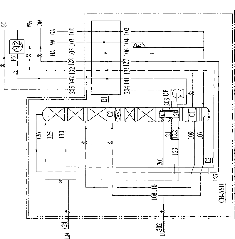
[0036] (1) Compressed and purified air GA is introduced into heat exchanger E1 through pipeline 101 for low-temperature cooling;
[0037] (2) The cooled air is sent into the lower tower C1 through the 102 pipeline, and the lower tower is carried out heat and mass transfer with the top-down liquid on the tray or packing from bottom to top in the lower tower, and nitrogen is obtained at the top of the lower tower;
[0038](3) The nitrogen generated from the top of the lower tower is divided into two bundles, one of which is sent to the heat exchanger E1 through the pipeline 141 to be reheated to normal temperature, and is drawn out as the pressure nitrogen product PN through the pipeline 142, and the nitrogen product can be directly used as required. Send it to the user's nitrogen pipe network or send it to the user's nitrogen pipe network after being pressurized by the booster NZ to the required pressure; the second bundle of nitrogen enters the condensing evaporator K1 and is c...
Embodiment 2
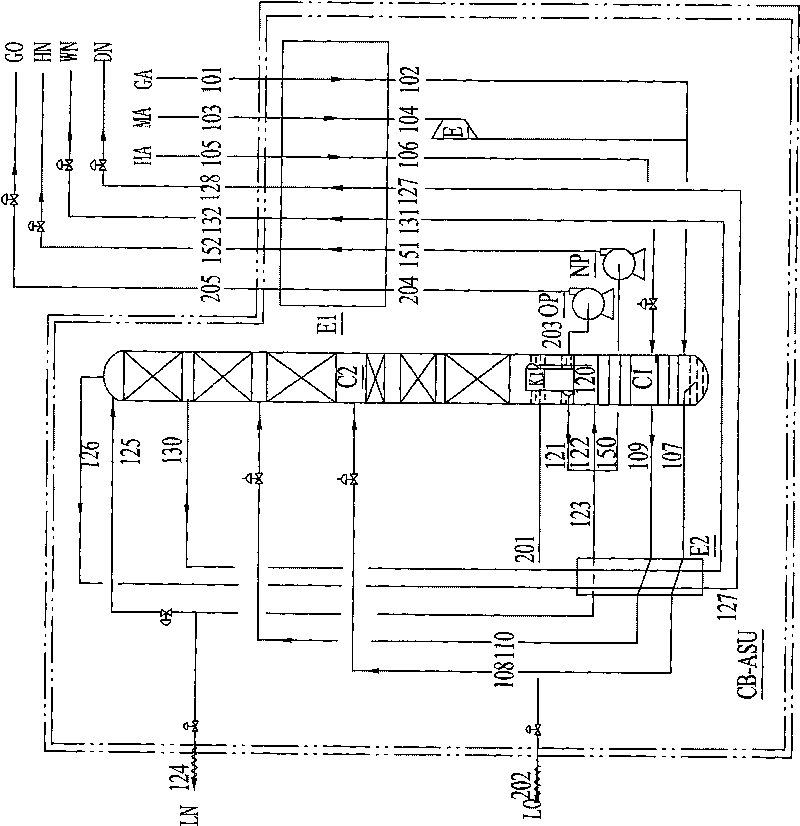
[0046] The difference between technological process of the present invention and embodiment 1 is:
[0047] Step (3) the nitrogen obtained from the top of the lower tower enters the condensing evaporator K1 and is condensed into liquid nitrogen;
[0048] The condensed liquid nitrogen in step (4) is divided into three bundles, one bundle of liquid nitrogen enters the subcooler E2 through the 121-123 pipeline, and the supercooled liquid nitrogen is divided into two bundles again, and one bundle enters the upper tower C2 through the pipeline 125 The top is used as the reflux liquid for rectification, and the other is drawn through the pipeline 124 as the product liquid nitrogen LN; the condensed second liquid nitrogen enters the lower tower through the 121-122 pipeline as the reflux liquid to continue the rectification; the condensed third liquid nitrogen Nitrogen enters the liquid nitrogen pump NP through the 150 pipeline and is compressed, then sent to the heat exchanger through...
Embodiment 3
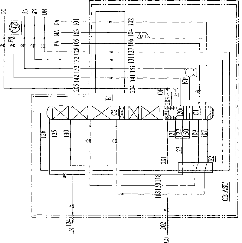
[0051] The process flow of the present invention is the combination of embodiment 1 and embodiment 2, that is, it differs from the steps of embodiment 1 in that:
[0052] Step (3) The nitrogen generated from the top C1 of the lower tower is divided into two bundles, one of which is sent to the heat exchanger through the 141 pipeline to be reheated to normal temperature, and is drawn out as the pressure nitrogen product PN through the 142 pipeline, and then passed through the booster NZ pressurized to the required pressure. The second beam of nitrogen enters the condensing evaporator K1 and is condensed into liquid nitrogen;
[0053] The condensed liquid nitrogen in step (4) is divided into three bundles, one bundle of liquid nitrogen enters the subcooler E2 through the 121-123 pipeline, and the supercooled liquid nitrogen is divided into two bundles again, and one bundle enters the upper tower C2 through the pipeline 125 The top is used as the reflux liquid for rectification,...
PUM
 Abstract
Description
Claims
Application Information